Hellloo BTE3232 Students,
Welcome back to UMPSA. Than you for registering into this course BTE 3232 Communication System Design Laboratory.
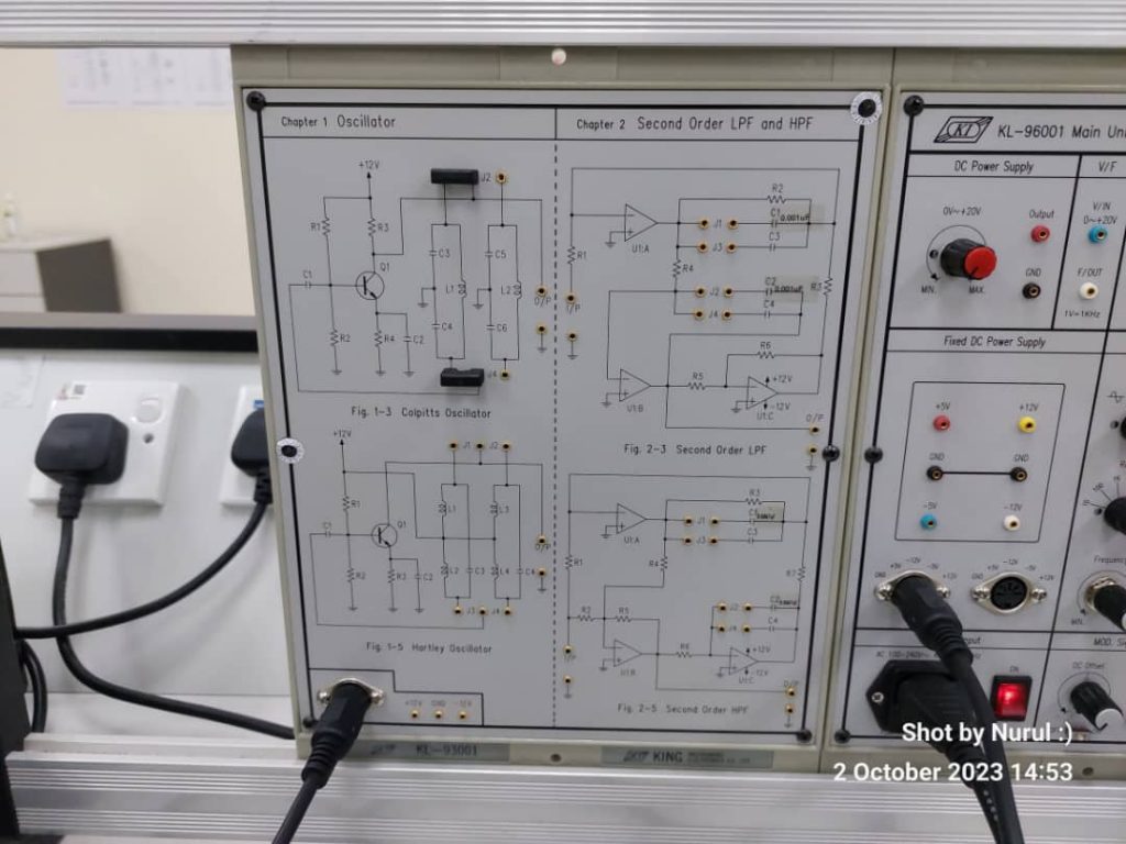
I hope this message finds you well and thriving in your exploration of the fascinating world of communication system design. Today, we’ll kick off with Lab No. 1, where we embark on a journey to understand the details of the Colpitt and Hartley Oscillators – crucial components in the superheterodyne radio receivers.
Colpitt Oscillator: A Stable Foundation for RF Systems
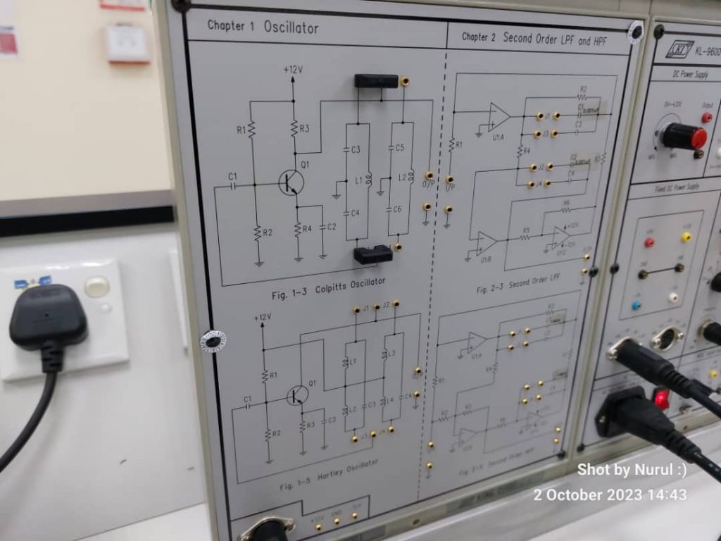
As we venture into the heart of this laboratory exercise, let’s first look the concept of the Colpitt Oscillator. Named after its inventor Edwin Colpitts, this oscillator plays a pivotal role in generating the desired frequency for radio frequency applications, making it an indispensable element in communication systems.
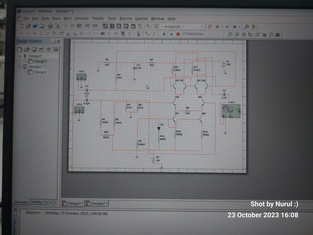
As you may have seen the lab instructions, the Colpitts Oscillator takes center stage due to its ability to provide a stable and tunable output frequency – an essential characteristic for effective communication. Its configuration, comprising a transistor, capacitors, and inductors, allows it to produce a continuous oscillation that we can harness for various communication purposes.
Hartley Oscillator: A Harmonious Alternative
Now, let’s introduce the Hartley Oscillator, an alternative configuration, named after its inventor Ralph Hartley, this oscillator also contributes significantly to communication system design.
The Hartley Oscillator, like the Colpitts, is commonly employed for its stability and frequency-tuning capabilities. However, its distinctive feature lies in the use of a tapped inductor, creating a center tap that allows for enhanced coupling between the inductor and the capacitor, promoting a more efficient oscillation.
Comparing Colpitts and Hartley Oscillators:
To better understand the nuances of these two oscillators, let’s delve into a table comparison:
| Feature | Colpitts Oscillator | Hartley Oscillator |
|---|---|---|
| Configuration | Single inductor, single capacitor | Tapped inductor, single capacitor |
| Tuning Range | Narrow | Wide |
| Frequency Stability | Good | Excellent |
| Amplitude Stability | Moderate | Good |
| Common Applications | RF applications, low-frequency VCO | RF applications, audio oscillators |
Understanding the Significance of Capacitance and Inductance:
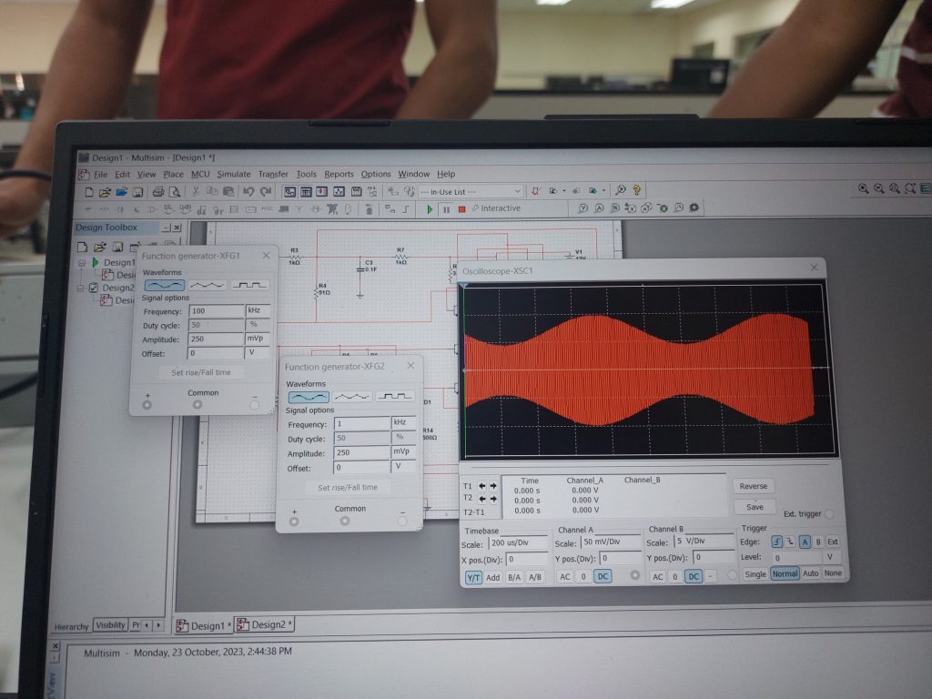
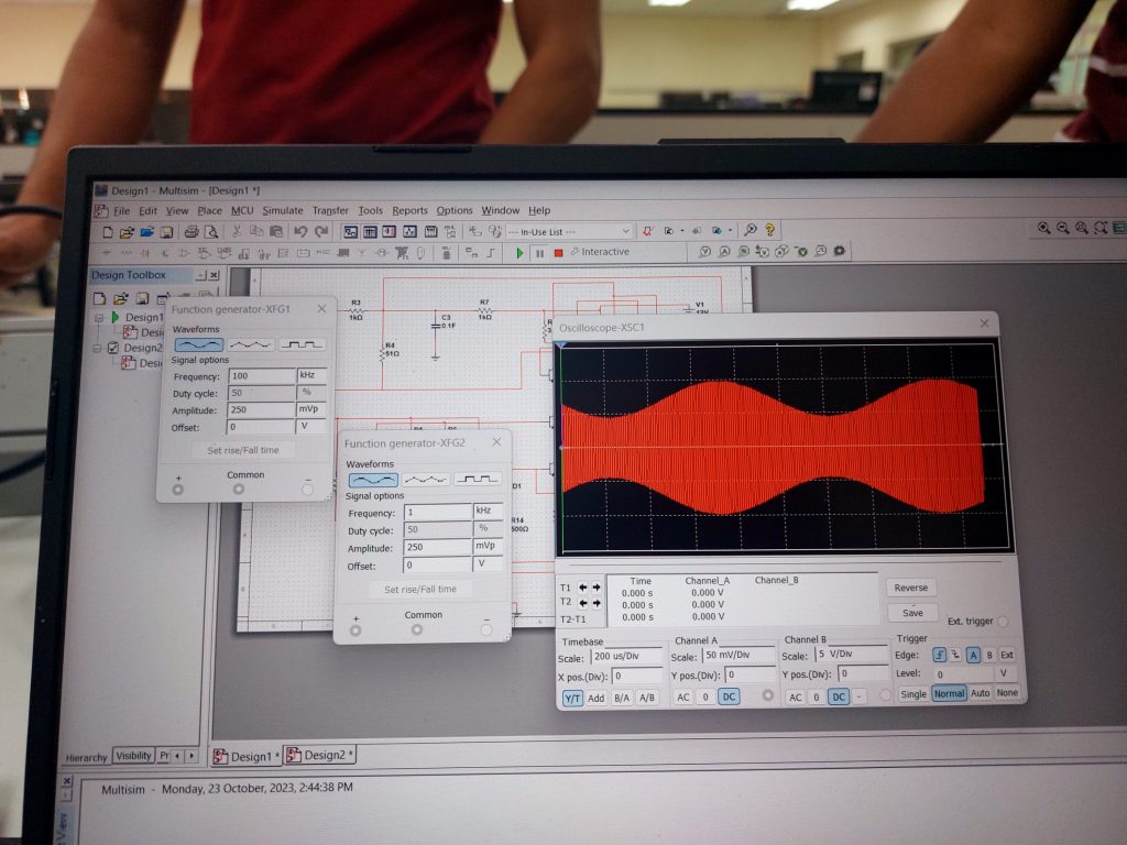
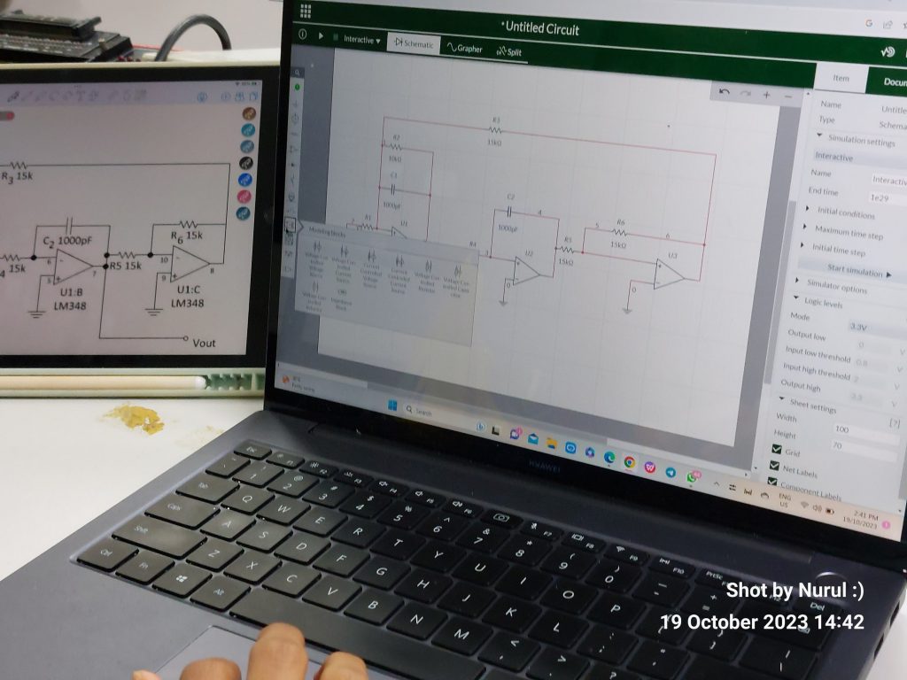
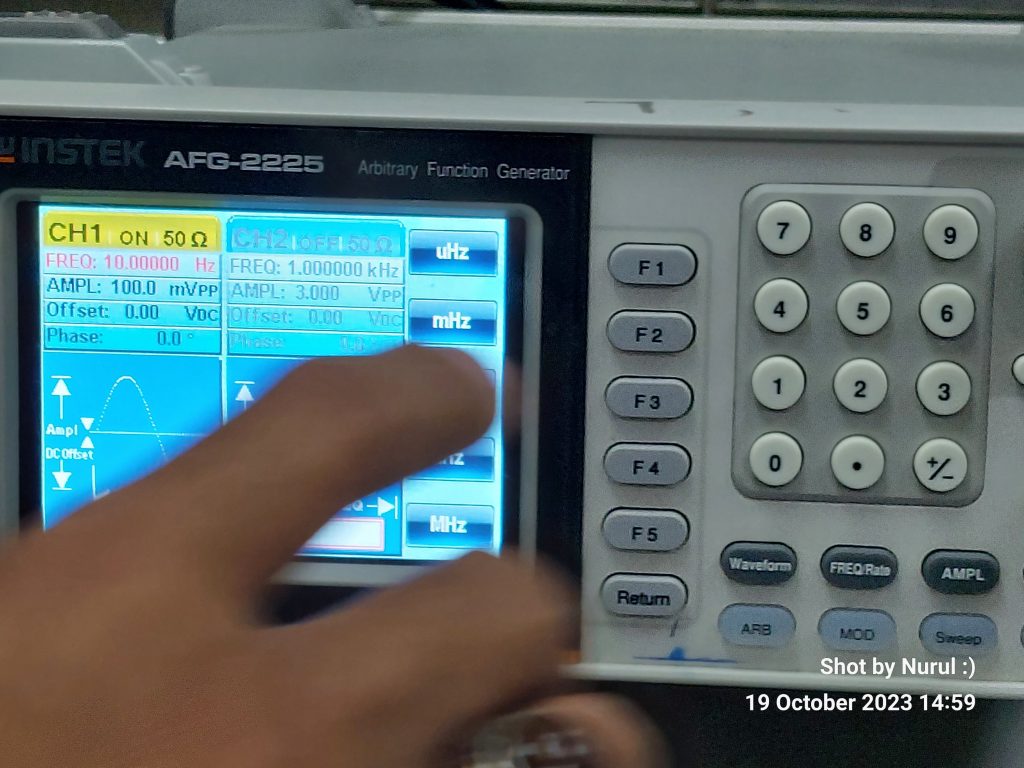
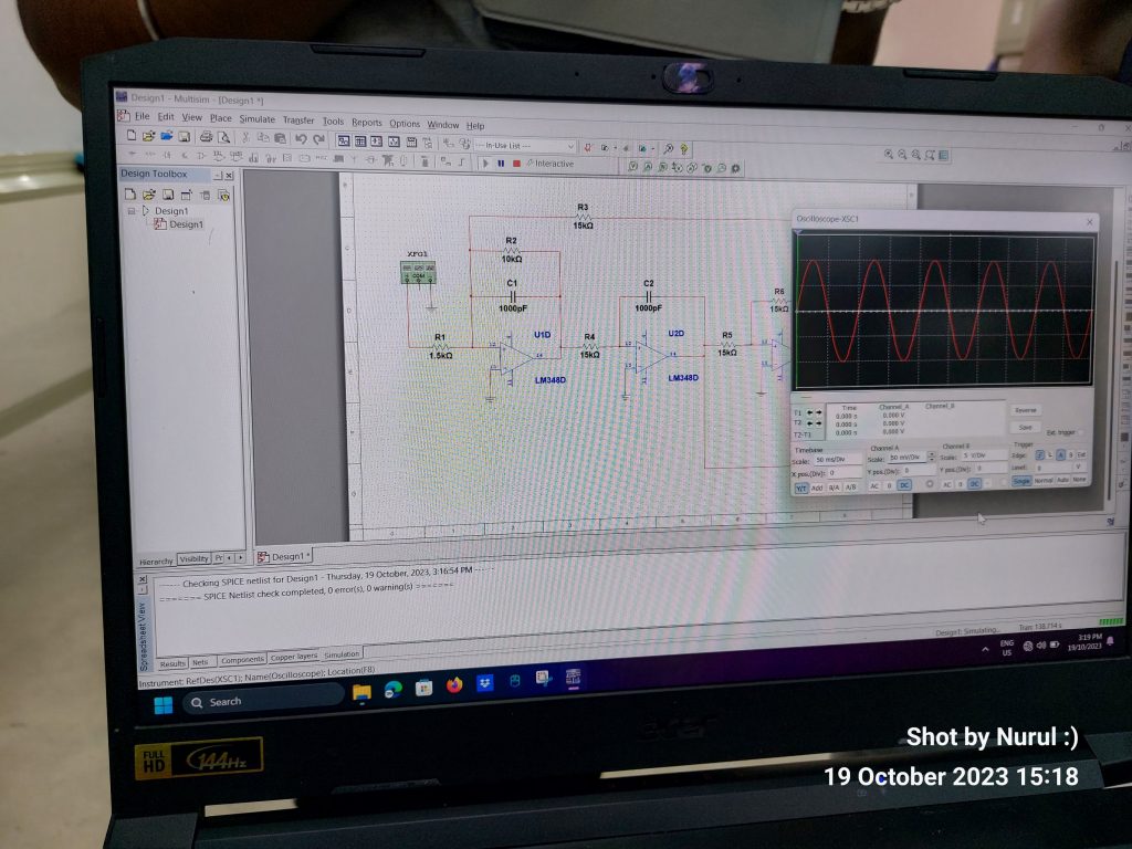
In the context of both the Colpitts and Hartley Oscillators, capacitance and inductance values are crucial parameters that significantly influence the frequency of oscillation, stability, and overall performance. As you engage in Lab 1, experiment with different values for capacitors and inductors in both oscillator configurations to observe their effects on frequency, stability, and amplitude.
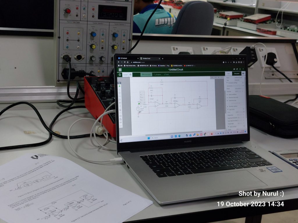
This hands-on experience will not only reinforce theoretical concepts but also sharpen your skills in communication system design. Remember, a deep understanding of the Colpitts and Hartley Oscillators empowers you to engineer communication systems with precision and finesse.
Please submit your lab report by Friday March 8th, 2024 – hardcopy. And upload on Kalam.
Nurul – March 3rd, 2024