Tech Talk 2024/2 – Advance Wireless Communications

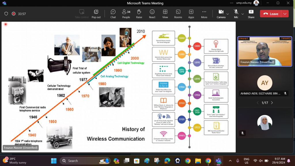
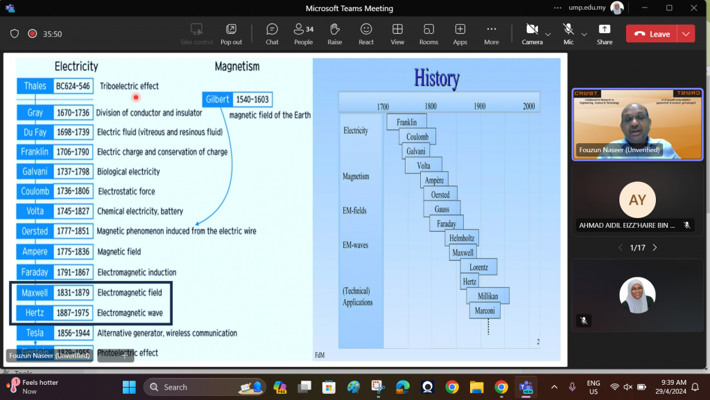
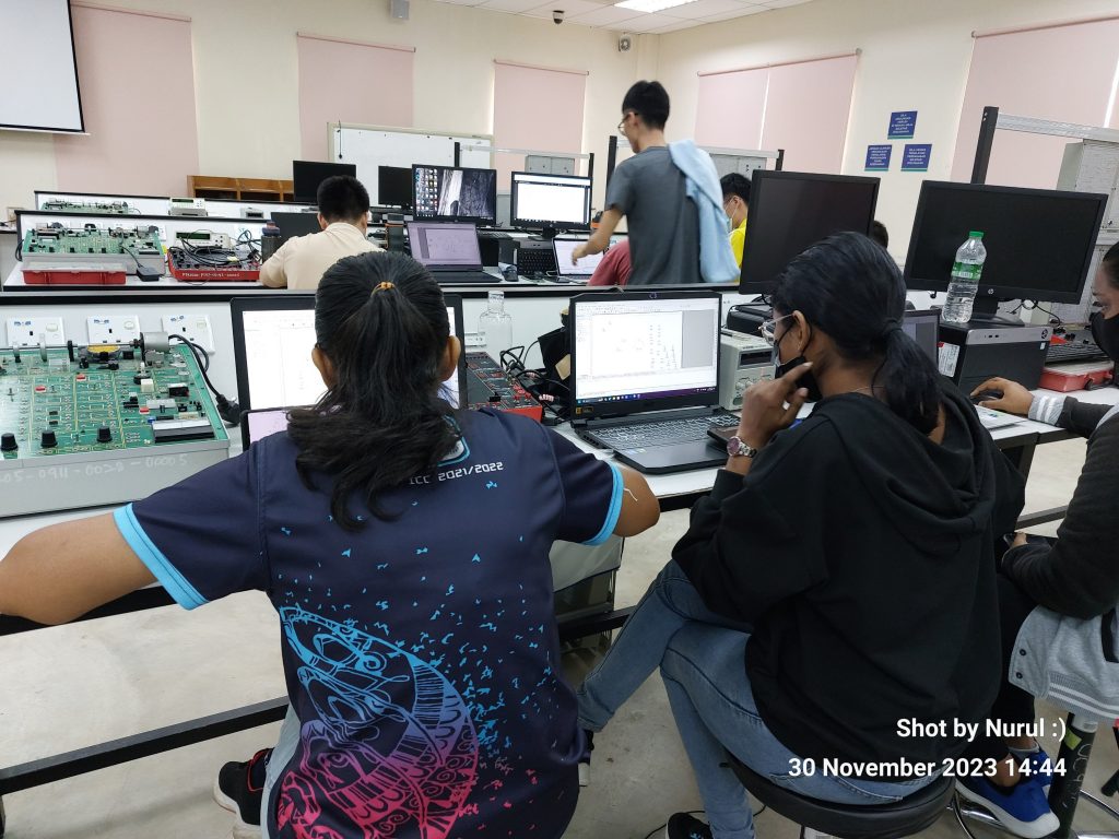
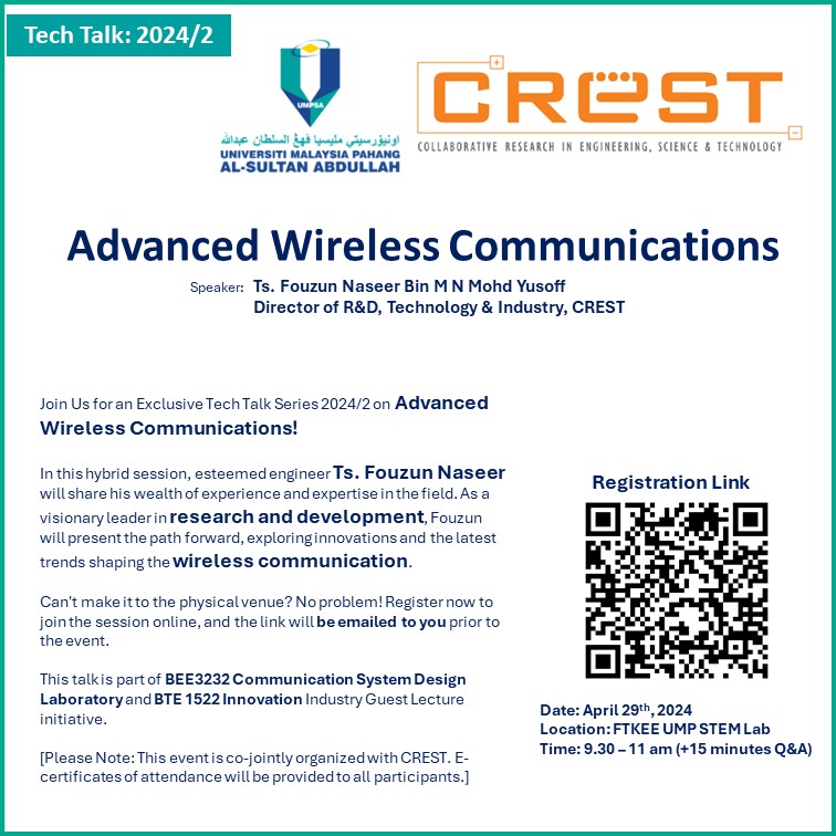
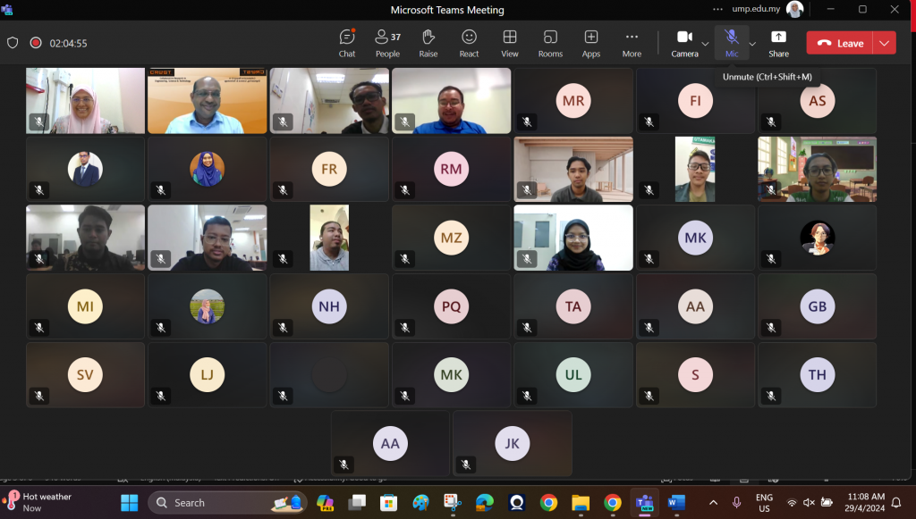
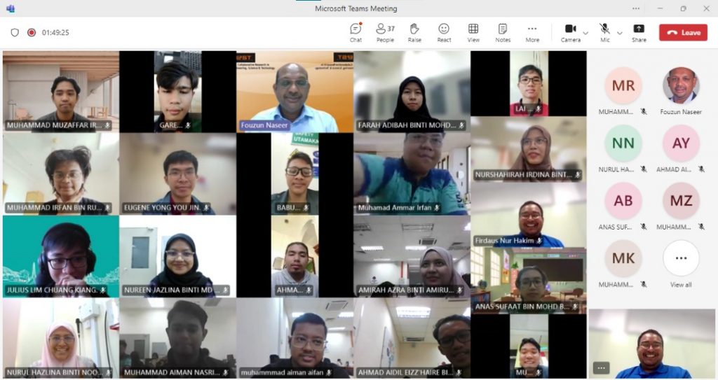
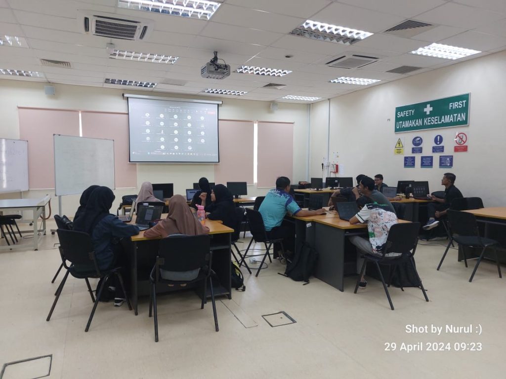
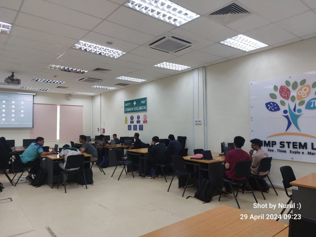
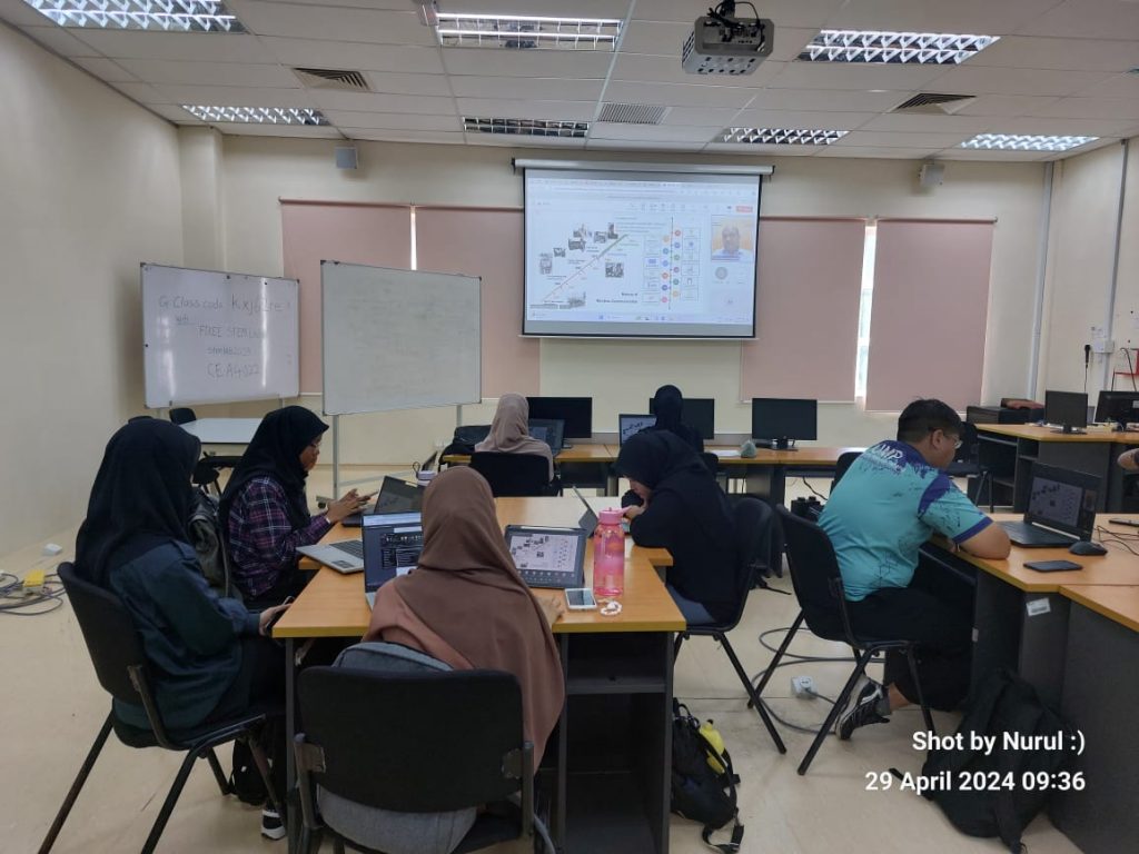
Today’s industrial talk session at UMP STEM Lab =), featuring an experienced speaker,  Ts Fouzun Nassir, R&D Director of CREST (https://crest.my/). Mr Fouzun delved into the subject of advanced wireless communication. The two-hour discussion was filled with engaging insights and thought-provoking questions, addressing various aspects of the communication technology. Let’s explore some of the key topics discussed during the session:

  1. The Decline of Ericsson and Nokia in Today’s Phone Market –
    Ericsson and Nokia, once giants in the early days of wireless communication, have seen a decline in their relevance in today’s phone market. Factors contributing to this decline include increased competition from emerging players, failure to adapt quickly to changing market trends, and perhaps complacency in innovation. To regain relevance, Ericsson and Nokia could focus on diversifying their product offerings, investing more in research and development, forging strategic partnerships, and enhancing their brand image through marketing and customer engagement initiatives.
  2. The Persistence of 2G Networks Despite 5G Advancements –
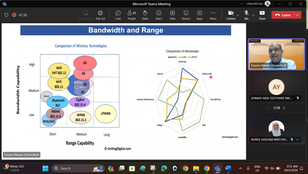
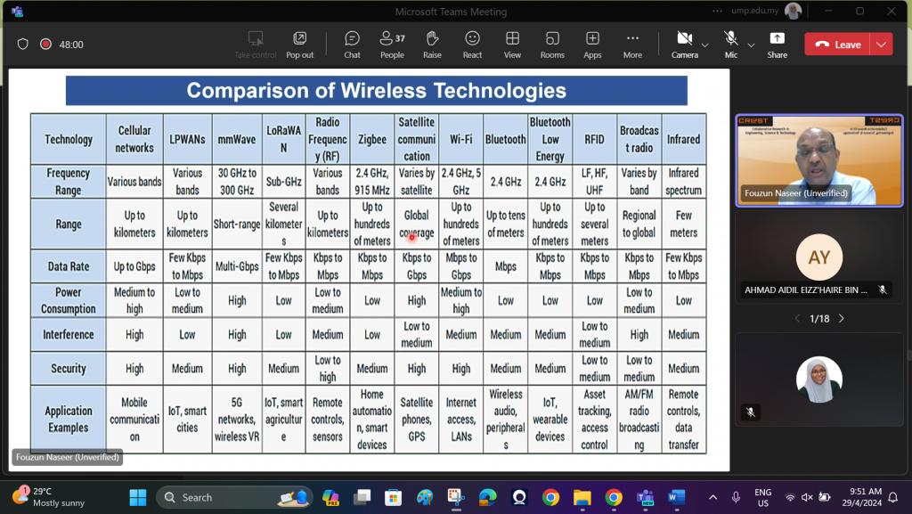
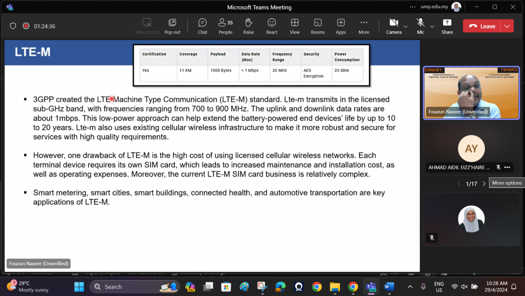
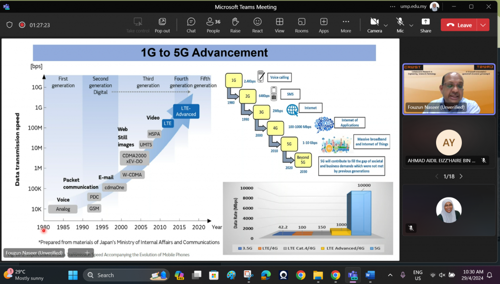
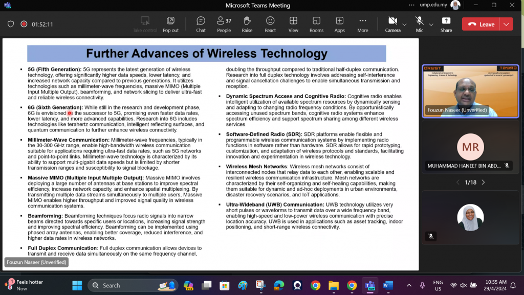
    Despite the advancements in 5G technology, there is still a reliance on 2G networks in certain regions or applications. This reliance can be attributed to several factors such as cost-effectiveness, backward compatibility with older devices, and the availability of infrastructure in remote or rural areas. Additionally, 2G networks are often used for essential services like voice calls and messaging in regions where 5G infrastructure is not yet widespread.
  3. The Role of AI/ML in Improving Wireless Communication Systems-
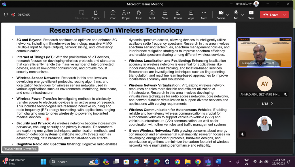
    AI and ML technologies play a crucial role in optimizing network performance and spectrum utilization in wireless communication systems. By analyzing vast amounts of data, AI algorithms can dynamically adjust network parameters, predict user behavior, and optimize resource allocation. This leads to improved network efficiency, reduced latency, and enhanced user experience.
  4. Addressing Security and Privacy Concerns in Communication and IoT Projects –
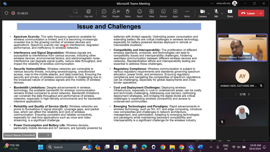
    With the proliferation of communication and IoT projects, security and privacy have become major concerns. Advanced systems employ robust encryption techniques, authentication mechanisms, and intrusion detection systems to safeguard user data against evolving cybersecurity threats. Additionally, privacy-enhancing technologies such as differential privacy and homomorphic encryption are being explored to protect sensitive information.
  5. Future Applications of NFC Technology in Malaysia –
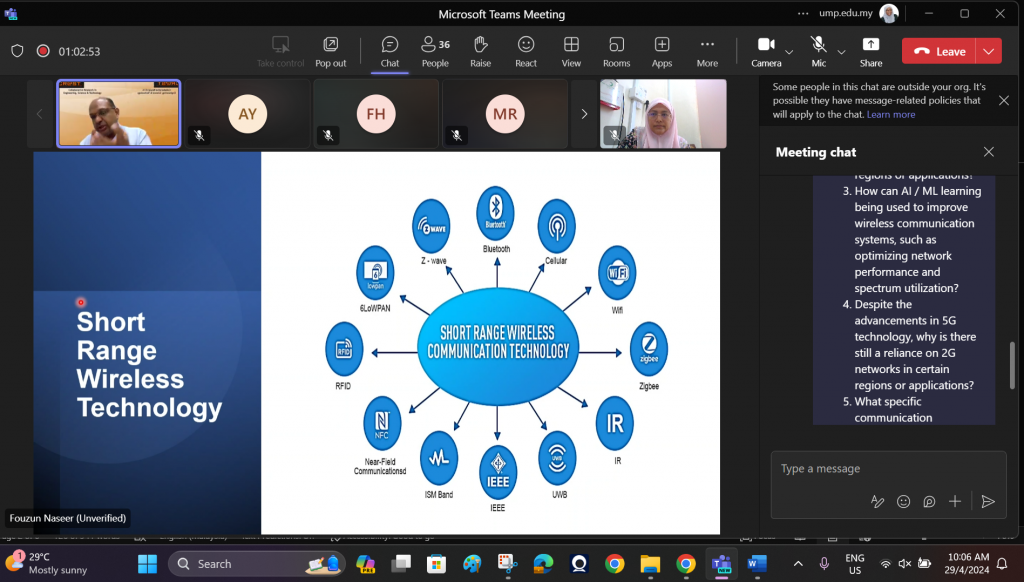
    Beyond payments, NFC technology holds potential for various applications in Malaysia, including transportation ticketing, access control, healthcare data management, and retail loyalty programs. Initiatives are underway to explore these applications further and harness the full potential of NFC technology in enhancing convenience and efficiency across various sectors.
  6. Environmental Sustainability in the Communications Hardware Industry –
    As we strive for environmental sustainability and compliance with Sustainable Development Goals (SDGs), the communications hardware industry is adopting various methods to reduce electronic waste. This includes recycling programs, eco-friendly manufacturing processes, and designing products with longevity and recyclability in mind. Additionally, initiatives are being undertaken to promote the circular economy and minimize the environmental impact of communication technology.
  7. The Potential Concerns Surrounding the Development of 6G –
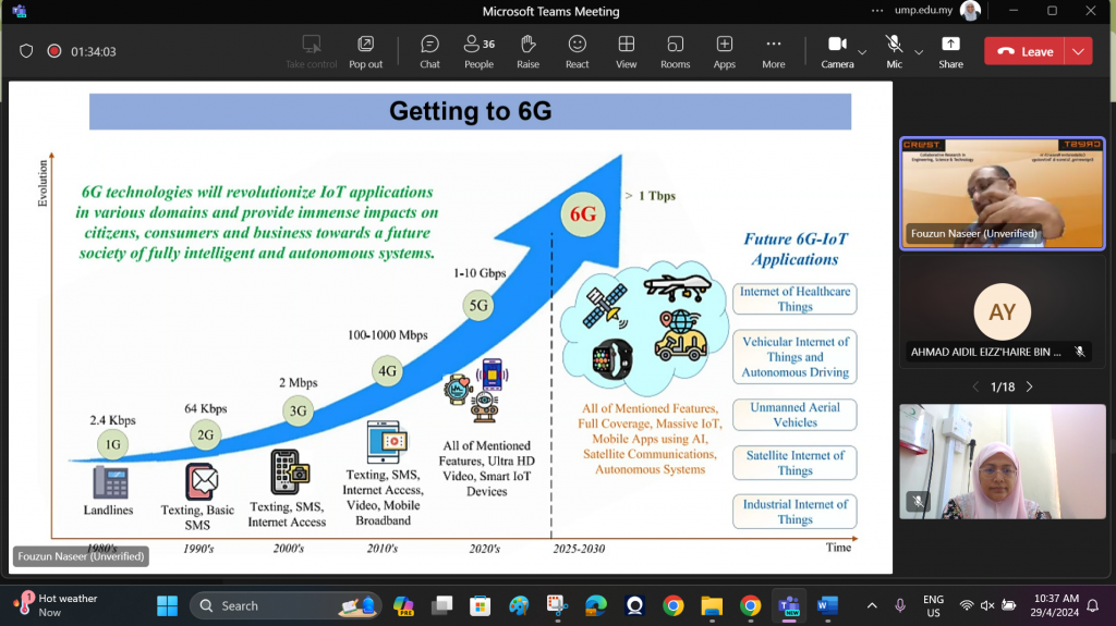
    There is a concern that the development of 6G may be more closed-source than 5G, potentially hindering innovation and progress. Unlike the collaborative and open approach seen in the development of 5G standards, the race to develop 6G technologies may lead to proprietary solutions and fragmented ecosystems. This could limit interoperability, stifle competition, and impede the widespread adoption of 6G technology.

The talk by En Fouzun Nassir provided valuable insights into the complexities and future prospects of wireless communication. Especially for BTE 3232 students, Communication System Design Laboratory.

Today’s tech talk by En Fouzun Nassir marks an exciting initiative in UMP STEM Lab Tech Talk 2024/2 series, aimed at bridging the gap between industry expertise and student learning. With a focus on the subject of BTE 3232 Communication System Design Lab, esteemed experts from various fields come together to share their wealth of experience and insights with students. These talks serve as invaluable opportunities for students to gain firsthand knowledge, engage with industry professionals, and enrich their understanding of real-world applications in communication system design.

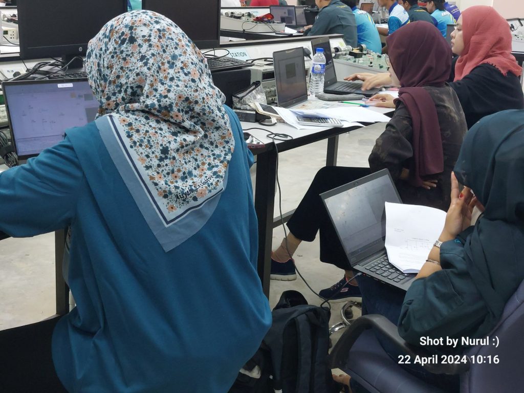
To all BTE 3232 students, thank you very much for your active participations throughout the talk =).

Nurul Hazlina Noordin

April 29th, 2024

BTE3232 – Communication System Design Laboratory Assignment

1.  Project Assignment Overview

The project assignment for BTE 3232 Communication System Design Laboratory is designed to provide students with practical experience and insight into various aspects of communication systems. The assignment comprises three segments:

  1. Write a review on current trends in wireless communication systems.
  2. Report on a visitation to KLCC Petronas Twin Tower communication room.
  3. Design communication circuit construction and simulation.

Each segment carries equal weightage and contributes 40% towards the overall assessment.

2.  Segment 1: Review on Current Trends in Wireless Communication Systems

Instructions

  • Conduct research on current trends, advancements, and emerging technologies in wireless communication systems.
  • Ask good quality questions.
  • Write a comprehensive review highlighting key developments, challenges, and future prospects in the field.
  • Ensure the review is well-structured, with clear sections covering topics such as 5G technology, IoT applications, spectrum management, and beyond.

3.  Segment 2 – Report on Visitation to KLCC Petronas Twin Tower Communication Room

Instructions

  • Arrange a visitation to the communication room at KLCC Petronas Twin Towers.
  • Ask good quality questions.
  • Document observations, insights, and experiences during the visit.
  • Compile a detailed report outlining the infrastructure, equipment, and operations of the communication room.
  • Include photographs, diagrams, and any relevant documentation to enhance the report’s clarity and understanding.

4.  Segment 3 Design Communication Circuit Construction and Simulation

Instructions

  • Select a communication circuit project relevant to the course curriculum.
  • Design the circuit layout, considering factors such as component selection, wiring, and circuit configuration.
  • Construct the circuit according to the design specifications, ensuring accuracy and precision.
  • Simulate the circuit using appropriate software tools to validate functionality and performance.

5.  Submission Guidelines:

  • Each segment must be submitted individually within the specified deadline.
  • Submit reports in a digital format, adhering to the prescribed format and guidelines.
  • Late submissions will incur penalties as per the course policy.


Rubric


BTE3232 – Com System Design – FM Modulators and Demodulators

Hi BTE1522-ian,

Salam Ramadhan Al-Mubarak.

Today in our lab sessions, we looked into the Frequency Modulation (FM) modulation and demodulation technique. This hands-on experience not only offers insight into the fundamentals of communication systems but also provides a practical understanding of why FM remains a preferred choice in the broadcasting industry, yepp until today!

Lab 7: FM Modulator – the Essence of Frequency Modulation

In Lab 7, we explored the concept behind Frequency Modulation (FM), a modulation technique widely employed in radio broadcasting and communication systems. FM involves varying the frequency of a carrier signal in accordance with the amplitude of the modulating signal. But why do radio stations still predominantly utilize FM over other modulation techniques?

One primary reason is its superior resistance to noise. Unlike Amplitude Modulation (AM), which suffers from susceptibility to atmospheric interference and electrical noise, FM offers better fidelity and clarity in signal transmission. This is crucial for broadcasting music and speech, ensuring high-quality audio reception for listeners.

Moreover, FM allows for efficient bandwidth utilization. By varying the frequency of the carrier signal, FM can accommodate a wide range of audio frequencies within a smaller bandwidth, making it more spectrum-efficient compared to AM.

Building Your Own FM Transmitter: A Fascinating Project

Constructing your own FM transmitter can be an exciting project, offering hands-on experience and a deeper understanding of FM modulation principles. By employing basic electronic components such as oscillators, modulators, and antennas, you can create a simple yet functional FM transmitter. This project not only reinforces theoretical concepts but also fosters creativity and problem-solving skills.


Lab 8: FM Demodulator – Deciphering the Magic of FM Demodulation

In Lab 8, we explored FM demodulation techniques, which are essential for retrieving the original modulating signal from an FM modulated carrier wave. Two common demodulation methods used are Phase-Locked Loop (PLL) and Frequency Discriminator (FM-AM discriminator).

PLL demodulation relies on a feedback loop to synchronize the phase of a local oscillator with the incoming FM signal. This synchronized oscillator produces an output voltage proportional to the frequency deviation of the FM signal, allowing for accurate demodulation.

On the other hand, FM-AM discriminator demodulation capitalizes on the frequency-to-amplitude conversion characteristic of FM signals. By passing the FM signal through a frequency-selective circuit, variations in frequency translate into variations in amplitude, which can then be extracted as the modulating signal.

Building Your Own FM Receiver: A Captivating Endeavor

Constructing an FM receiver offers a rewarding experience, enabling you to tune in to your favorite radio stations and explore the world of wireless communication firsthand. With components such as antennas, tuned circuits, and detectors, you can assemble a basic FM receiver capable of capturing and demodulating FM signals. This project not only enhances technical skills but also fosters a deeper appreciation for the intricacies of communication systems.


In conclusion, our lab experiments in FM modulation and demodulation provide invaluable insights into the design and operation of communication systems. By understanding the principles behind FM modulation and demodulation, as well as engaging in hands-on projects, we can further enrich our knowledge and appreciation for the fascinating world of wireless communication.

Keep exploring, keep learning, and let your curiosity guide you on this exciting journey of discovery!

BTE3232 – CSD Lab – SSB Modulation / Demodulation

Single Sideband and Double Sideband Technique: Yet another Analog Carrier Modulation
As we look into the details of communication system design, understanding the fundamental of modulation techniques is crucial. In today’s laboratory session, we explored the Single Sideband (SSB) and Double Sideband (DSB) modulation and demodulation.

Before going into the practical aspects of our lab assignment, let’s take a recap the significance of passband in the context of these modulation techniques.

Modulation Techniques


While digital modulation techniques dominate contemporary communication systems, our focus in BTE3233 remains on analog carrier modulation techniques. These techniques, steeped in tradition, offer invaluable insights into the evolution of modern modulation methods.

SSB and DSB Modulation
SSB and DSB modulation techniques offer unique advantages over traditional Amplitude Modulation (AM) and Frequency Modulation (FM) methods. Despite the widespread adoption of AM and FM in various communication applications, SSB and DSB modulation techniques continue to hold relevance due to their efficient utilization of passband.


In the frequency spectrum, Single Sideband (SSB) modulation exhibits a distinctive characteristic compared to traditional Amplitude Modulation (AM). Unlike AM, which transmits both sidebands along with the carrier signal, SSB modulation only transmits either the upper sideband (USB) or the lower sideband (LSB) along with the carrier. As a result, SSB modulation effectively utilizes half of the bandwidth required by AM, leading to enhanced spectral efficiency.

In the frequency domain, SSB modulation produces a spectrum with a single sideband extending from either side of the carrier frequency, with the other sideband and the carrier suppressed. This concentrated spectral distribution enables SSB signals to occupy a narrower bandwidth, making them ideal for conserving precious frequency resources while maintaining signal integrity. During demodulation, the suppressed sideband is effectively reconstructed, ensuring faithful reproduction of the original message signal. Thus, in the frequency spectrum, SSB modulation and demodulation techniques showcase a streamlined and efficient utilization of frequency resources, paving the way for optimized communication system design.

Advantages of SSB and DSB Modulation

  1. Enhanced Bandwidth Utilization: SSB and DSB modulation techniques optimize spectral efficiency by transmitting either one sideband (SSB) or both sidebands (DSB) along with the carrier. This efficient use of bandwidth ensures optimal utilization of the passband, making these techniques ideal for bandwidth-limited communication channels.
  2. Power Efficiency: By eliminating redundant components such as the carrier and one sideband (in the case of SSB), these modulation techniques enhance power efficiency during transmission. This translates to improved signal-to-noise ratio and reduced power consumption, contributing to overall system performance.
  3. Reduced Interference: SSB and DSB modulation techniques minimize interference with adjacent channels by transmitting only essential spectral components within the passband. This reduction in interference enhances signal clarity and reception quality, particularly in environments with high spectral congestion.


As we went through our lab assignment today focusing on SSB modulation and demodulation, it’s essential to recognize the pivotal role of passband in shaping the efficiency and effectiveness of these modulation techniques. Note that the advantages of SSB and DSB modulation, enable the possibility to design robust and efficient communication systems that thrive within the constraints of the passband.

Stay tuned for our upcoming lab session (FM Mod & Demodulation), where we’ll translate theory into practice and delve deeper into the practical implementation of Frequency Modulation and its demodulation techniques.

Get ready to explore the fascinating world of frequency-based communication, where signals dance across the spectrum with precision and clarity. Don’t miss out on this exciting opportunity to expand your skills and understanding in communication engineering. See you in the lab!

BTE3232 – Communications Systems Design Lab – Amplitude Modulation and Demodulation

Today is Lab 3 and Lab 4 – which focuses on AM modulation and AM demodulation. Understanding these important concepts in radio technology is paramount for success in our Communication System Design Laboratory class, as they form the foundation for efficient signal transmission and reception.


Why Modulate Signals?

To comprehend the significance of modulation, let’s first consider the limitations of transmitting a signal in its raw form. A simple, unmodulated signal lacks the resilience needed to combat issues like interference, noise, and attenuation over long distances. This is where modulation steps in as our technological superhero.

Amplitude Modulation involves varying the amplitude of a carrier signal in proportion to the instantaneous amplitude of the input signal. In simpler terms, it’s like riding the waves of your favorite radio station. The carrier wave carries the information from the input signal, effectively extending the reach and quality of the transmitted signal.

Why AM?

Now, you might wonder, “Why AM and not something else?” AM modulation has its unique advantages, such as simplicity, ease of implementation, and compatibility with various transmission mediums. However, it comes with challenges like susceptibility to noise and limited bandwidth efficiency, paving the way for modern modulation schemes.

In the ever-evolving landscape of communication systems, engineers sought to address the limitations of AM modulation. This led to the development of more sophisticated schemes like FM (Frequency Modulation) and PM (Phase Modulation). These modern modulation techniques offer improved noise resilience, better bandwidth utilization, and enhanced signal quality.

Demodulation: Unveiling the Message:

Now, let’s transition to the counterpart of our tale – demodulation. Demodulation is the process of retrieving the original signal from the modulated carrier wave. It’s like extracting the hidden treasure from the waves you’ve been riding. In our laboratory, we’ll explore demodulation techniques to decode the transmitted information accurately.

As we journey through the world of AM modulation and demodulation in our Communication System Design Laboratory, remember that these concepts are the cornerstone of effective signal transmission. Understanding the ‘why’ behind modulation and the advancements leading to modern schemes equips us to tackle real-world challenges in the dynamic field of electrical engineering.

So, gear up, future engineers! Let’s ride the waves of knowledge and explore the intricate dance between amplitude, frequency, and phase in the vast ocean of communication systems.


BTE3232 – Com System Design – Oscillators


Hellloo BTE3232 Students,

Welcome back to UMPSA. Than you for registering into this course BTE 3232 Communication System Design Laboratory.

I hope this message finds you well and thriving in your exploration of the fascinating world of communication system design. Today, we’ll kick off with  Lab No. 1, where we embark on a journey to understand the details of the Colpitt and Hartley Oscillators – crucial components in the superheterodyne radio receivers.

Colpitt Oscillator: A Stable Foundation for RF Systems

As we venture into the heart of this laboratory exercise, let’s first look the concept of the Colpitt Oscillator. Named after its inventor Edwin Colpitts, this oscillator plays a pivotal role in generating the desired frequency for radio frequency applications, making it an indispensable element in communication systems.

As you may have seen the lab instructions, the Colpitts Oscillator takes center stage due to its ability to provide a stable and tunable output frequency – an essential characteristic for effective communication. Its configuration, comprising a transistor, capacitors, and inductors, allows it to produce a continuous oscillation that we can harness for various communication purposes.

Hartley Oscillator: A Harmonious Alternative

Now, let’s introduce the Hartley Oscillator, an alternative configuration, named after its inventor Ralph Hartley, this oscillator also contributes significantly to communication system design.

The Hartley Oscillator, like the Colpitts, is commonly employed for its stability and frequency-tuning capabilities. However, its distinctive feature lies in the use of a tapped inductor, creating a center tap that allows for enhanced coupling between the inductor and the capacitor, promoting a more efficient oscillation.

Comparing Colpitts and Hartley Oscillators:

To better understand the nuances of these two oscillators, let’s delve into a table comparison:

Feature Colpitts Oscillator Hartley Oscillator
Configuration Single inductor, single capacitor Tapped inductor, single capacitor
Tuning Range Narrow Wide
Frequency Stability Good Excellent
Amplitude Stability Moderate Good
Common Applications RF applications, low-frequency VCO RF applications, audio oscillators

Understanding the Significance of Capacitance and Inductance:

In the context of both the Colpitts and Hartley Oscillators, capacitance and inductance values are crucial parameters that significantly influence the frequency of oscillation, stability, and overall performance. As you engage in Lab 1, experiment with different values for capacitors and inductors in both oscillator configurations to observe their effects on frequency, stability, and amplitude.

This hands-on experience will not only reinforce theoretical concepts but also sharpen your skills in communication system design. Remember, a deep understanding of the Colpitts and Hartley Oscillators empowers you to engineer communication systems with precision and finesse.

Please submit your lab report by Friday March 8th, 2024 – hardcopy. And upload on Kalam.

Nurul – March 3rd, 2024

BTE 3232 Communication System Design – Test 2 – The Timeless Elegance of AM Modulation in the Era of 5G :)

Dear BTE-ian,

So, today is Test 2.

I am thrilled to witness your dedication and enthusiasm as you tackle Test 2 :), delving into the intricate world of Amplitude Modulation (AM).

Even in today’s an era dominated by the marvels of 5G and cutting-edge communication systems, you might be wondering why we still have the fundamentals of AM modulation in  your syllabus…

Let me share some insights that highlight the enduring relevance of AM modulation, even in today’s rapidly advancing technological landscape.

The Time-Tested Elegance of AM Modulation
Amplitude Modulation is a technique that has stood the test of time, continues to play a crucial role in the context of communication systems. While it may seem like a relic of the past, AM modulation possesses certain attributes that make it indispensable, particularly in certain applications.

1. Robustness and Simplicity
One of the key reasons for the enduring relevance of AM lies in its robustness and simplicity. Unlike more complex modulation schemes, AM is relatively straightforward to implement and offers robust performance in challenging environments. Its simplicity allows for cost-effective and energy-efficient communication solutions, making it an attractive choice for various applications, including broadcasting.

2. Efficient Use of Bandwidth
AM modulation utilizes bandwidth efficiently, a characteristic that becomes increasingly important in the era of spectrum scarcity and the proliferation of wireless devices. In scenarios where bandwidth is a precious resource, AM modulation provides an effective means of transmitting information without imposing excessive demands on the available frequency spectrum.

AM Modulation in the Heterogeneous Radio Structure
As we navigate through the intricacies of modern communication systems, the concept of a heterogeneous radio structure becomes paramount. In this context, AM modulation finds its place alongside more advanced modulation schemes within a diversified framework.

1. Complementing Digital Communication
While digital modulation techniques dominate the landscape, AM modulation complements these methods in a heterogeneous radio structure. It can coexist harmoniously with digital signals, offering versatility in addressing different communication requirements.

Recall the heterogenous radio structure in this video, shared in week 1 before:-

2. Niche Applications
AM modulation is well-suited for niche applications, such as long-range broadcasting and point-to-point communication. In the heterogeneity of today’s communication landscape, where diverse needs must be met, AM modulation provides a valuable tool in the engineer’s arsenal.

The Wider Picture: AM Modulation in the Age of 5G
As you tackle Test 2, it’s essential to understand that while 5G and advanced communication systems are at the forefront of technological innovation, the foundations laid by AM modulation still influence the broader picture. The principles you are learning in this laboratory are building blocks that contribute to your understanding of the dynamic and evolving world of communication systems.

To all my Section 1 students in BTE 3232 Communication System Design Laboratory, I extend my heartfelt wishes for success in Test 2. Embrace the challenges with the knowledge that you are acquiring skills that will serve you well in the ever-evolving field of electrical and electronics engineering.

May your understanding of AM modulation be as clear as the signals it transmits, and may you emerge from this test with newfound insights and confidence. Best of luck!

Nurul – Jan 4th, 24

BTE 3233 – Communication System Design Lab Test 1

Hello BTE-ian,

All the best in your Test 1.  Remember to submit the following in KALAM:-

  1. Multisim Design File – both question 1 and 2
  2. Snapshot of the simulation output.

While you’re doing this 2-hour test (assessment marks of 20%), let me recap on the Oscillator topic that we did back in Week 1, the Hartley oscillator. A reminder of how significance it is in the context  communication system design, especially in the context of a communication system design laboratory.

The Hartley oscillator, named after its inventor Ralph Hartley, is a type of LC (inductor-capacitor) oscillator that generates sinusoidal waveforms. Its distinctive feature is the use of a tapped inductor in the tank circuit, which sets it apart from other LC oscillators like the Colpitts or Clapp oscillators.

Communication systems rely on oscillators for various functions, including frequency synthesis, modulation, and demodulation. The Hartley oscillator, with its stable frequency and simplicity in design, plays a pivotal role in ensuring the accuracy and efficiency of these processes.

Within the confines of a communication system design laboratory (our class it is 🙂 ), we engaged in the practical aspects of crafting communication systems – Lab 1. The Hartley oscillator is a common choice in these labs due to its straightforward design and ease of implementation, making it an excellent tool for learning the fundamentals of oscillator design and its integration into communication systems.

When designing an oscillator, several factors must be taken into account to ensure optimal performance. In the case of the Hartley oscillator, key considerations include:

  1. Frequency Stability: The oscillator must generate a stable frequency to prevent signal distortion. Careful selection of component values and precise tuning are essential.
  2. Amplitude Control: Maintaining a consistent amplitude output is crucial for reliable communication. Feedback mechanisms and component sizing play a role in achieving this stability.
  3. Start-Up Characteristics: Ensuring a quick and reliable start-up is vital for the oscillator to reach its stable operating point efficiently.

So, how do we describe a good oscillator?

The output of a Hartley oscillator is typically a sinusoidal waveform. This waveform can be characterized by parameters such as frequency, amplitude, and phase. In a communication system, understanding and controlling these parameters are essential for the successful transmission and reception of information.

The Hartley oscillator serves as a fundamental building block in communication systems, offering a reliable and efficient means of generating sinusoidal waveforms. Its simplicity makes it an ideal choice for educational purposes within communication system design laboratories, where students can gain hands-on experience in oscillator design and its integration into broader communication systems. As technology continues to advance, the role of oscillators like the Hartley oscillator remains pivotal in shaping the landscape of modern communication.

All the best everyone in answering your Test 1, and have a good holiday ahead. See you after the sem break.