BTE 3233 – Communication System Design Lab Test 1
Hello BTE-ian,
All the best in your Test 1. Remember to submit the following in KALAM:-
- Multisim Design File – both question 1 and 2
- Snapshot of the simulation output.
While you’re doing this 2-hour test (assessment marks of 20%), let me recap on the Oscillator topic that we did back in Week 1, the Hartley oscillator. A reminder of how significance it is in the context communication system design, especially in the context of a communication system design laboratory.
The Hartley oscillator, named after its inventor Ralph Hartley, is a type of LC (inductor-capacitor) oscillator that generates sinusoidal waveforms. Its distinctive feature is the use of a tapped inductor in the tank circuit, which sets it apart from other LC oscillators like the Colpitts or Clapp oscillators.
Communication systems rely on oscillators for various functions, including frequency synthesis, modulation, and demodulation. The Hartley oscillator, with its stable frequency and simplicity in design, plays a pivotal role in ensuring the accuracy and efficiency of these processes.
Within the confines of a communication system design laboratory (our class it is 🙂 ), we engaged in the practical aspects of crafting communication systems – Lab 1. The Hartley oscillator is a common choice in these labs due to its straightforward design and ease of implementation, making it an excellent tool for learning the fundamentals of oscillator design and its integration into communication systems.
When designing an oscillator, several factors must be taken into account to ensure optimal performance. In the case of the Hartley oscillator, key considerations include:
- Frequency Stability: The oscillator must generate a stable frequency to prevent signal distortion. Careful selection of component values and precise tuning are essential.
- Amplitude Control: Maintaining a consistent amplitude output is crucial for reliable communication. Feedback mechanisms and component sizing play a role in achieving this stability.
- Start-Up Characteristics: Ensuring a quick and reliable start-up is vital for the oscillator to reach its stable operating point efficiently.
So, how do we describe a good oscillator?
The output of a Hartley oscillator is typically a sinusoidal waveform. This waveform can be characterized by parameters such as frequency, amplitude, and phase. In a communication system, understanding and controlling these parameters are essential for the successful transmission and reception of information.
The Hartley oscillator serves as a fundamental building block in communication systems, offering a reliable and efficient means of generating sinusoidal waveforms. Its simplicity makes it an ideal choice for educational purposes within communication system design laboratories, where students can gain hands-on experience in oscillator design and its integration into broader communication systems. As technology continues to advance, the role of oscillators like the Hartley oscillator remains pivotal in shaping the landscape of modern communication.
All the best everyone in answering your Test 1, and have a good holiday ahead. See you after the sem break.
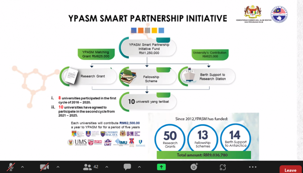
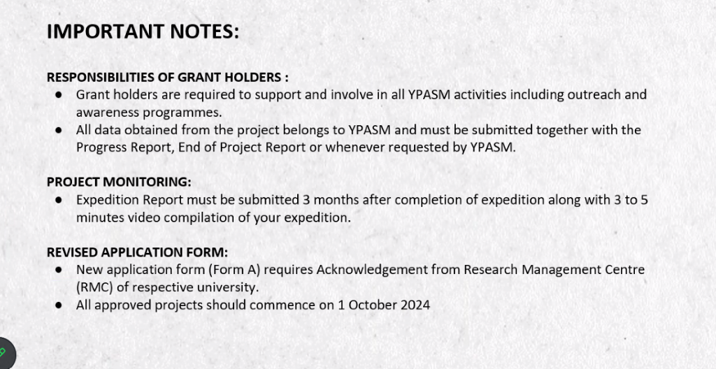
YPSAM – Research in /with Antartika :)





















DRE 2213 – Prog and Data Structure – Week 5
Hi DRE-ian,
The past 5 weeks, you’ve created your version of Slider Game. Throughout the development process, you’ve code the following in Python environment:-
- Game Window Properties (object oriented approach)
- Basic Programming Concepts in Python
- control statements
- Player Character Description,
- Programming Relevance – Python Basics
- Function Implementation
- Control Flow
- Player Movement Logic
- Programming Constructs
- Enemy Properties
- Programming Integration
- Enemy Behavior
- Scoring Logic
- Programming Elements
- Game Scoring Mechanism
- Logic Implementation
- Timing Systems,
- Data Structures
Wishing you all the best everyone in TEST 1 =)
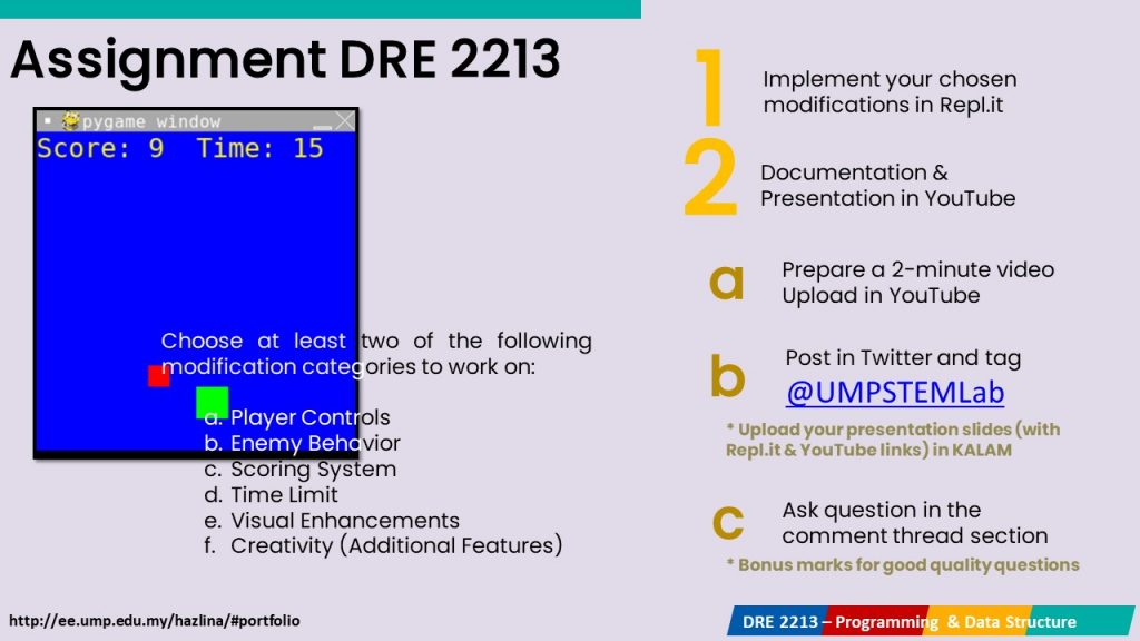
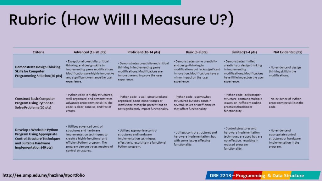
Also, remember to submit your Assignment 1 – assessment between Nov 8th – 18th.

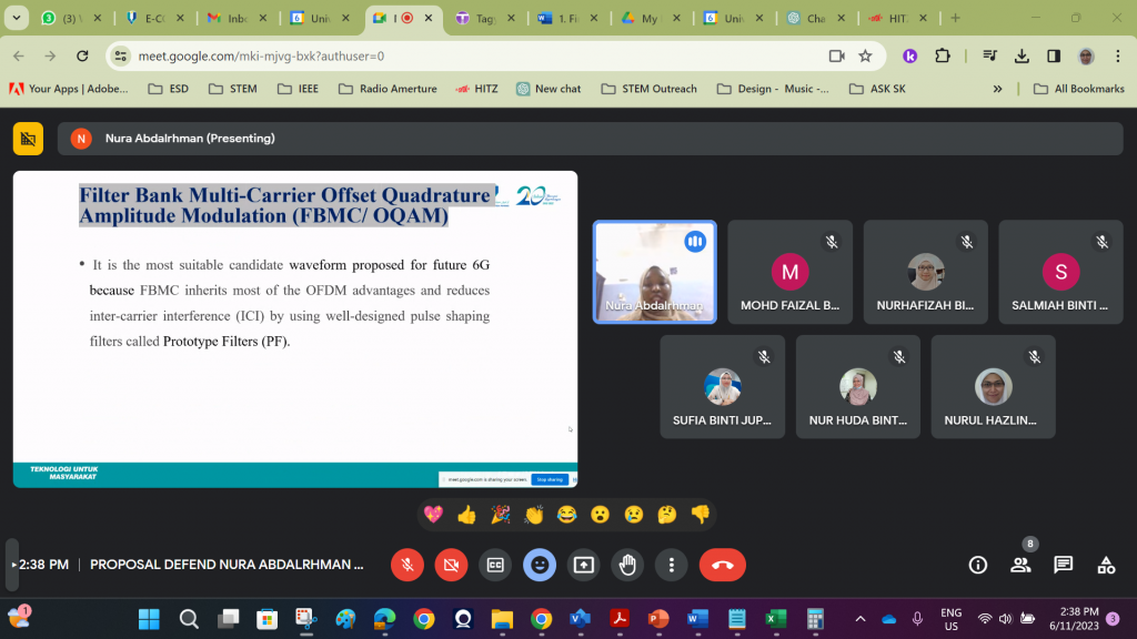
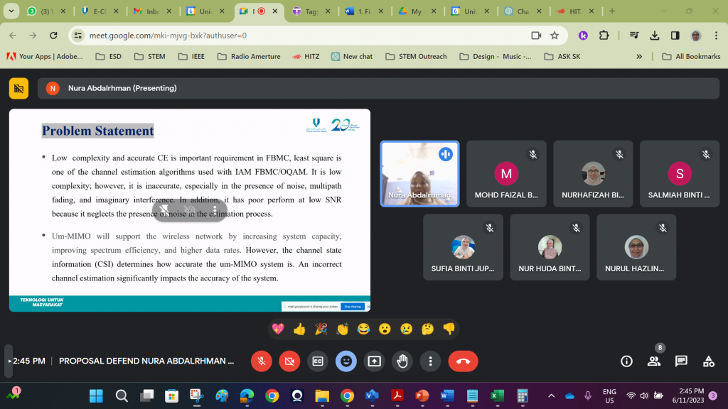
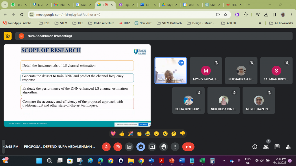
Proposal Defense – PhD in 6G



Movie Review 2023/5 – Yes It Could!

Semalam layan tgk movie ni dengan Baem. Best. A Disney documentary of Abby Road Studios – a name synonymous with musical legends, innovation, and timeless melodies. Nestled in the heart of London, this iconic studio has been a witness to over a century of musical history.
Narrated by Maria McCarthy, the daughter of the legendary Paul McCartney of The Beatles, exploring the rich legacy of this hallowed space.
Abbey Road Studios has a history dating back to the early 1900s. Since its inception, it has been a stage for some of the most well-known UK artists and musicians, and this tradition continues today. The walls of the studio are imbued with the echoes of countless legendary performances and recordings, making it a pilgrimage site for music enthusiasts worldwide.
1 – Mic tak rosak 🙂
One of the fascinating insights from the documentary is the simple yet crucial factor that keeps artists coming back to Abbey Road Studios—the functioning microphones. It may sound basic, but it’s often the small details that make or break a recording. A studio’s ability to maintain top-notch equipment is pivotal, ensuring that the artists’ creativity can be translated into timeless music.
2 – Pengaruh EMI to the Electronic Music Industry
The documentary focuses the role of Abbey Road Studios in the evolution of the electronic music industry. EMI, a renowned electronic music company, utilized the studio to produce records that reverberated worldwide. The fusion of cutting-edge electronics and music was a game-changer, and it’s a testament to the studio’s adaptability and innovation.
3 – Electronics and Innovation
The history of Abbey Road Studios underscores a broader truth about the world of invention. Electronics and engineering have played a pivotal role in transforming various aspects of our lives. Whether it’s in the field of medicine, agriculture, or music, innovation is often driven by advancements in electronic technology.
In the case of music, the fusion of analog and digital technology has led to groundbreaking advancements, revolutionizing the way we create and consume music.
Abbey Road Studios is not just a place – it’s a symbol (a ritual – bak kata one of the producers) of the harmonious coexistence of history and innovation. It’s where legends are born, music is immortalized, and the march of progress is embraced. The simple yet profound allure of functioning microphones, combined with the studio’s role in the electronic music industry, exemplifies the ever-evolving relationship between technology and creativity. The world of music, like so many others, has been forever transformed by the magic that happens within the walls of Abbey Road Studios.
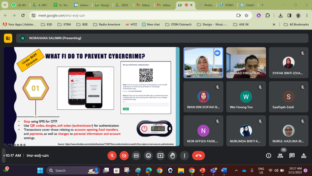
Cybercrime Seminar @ FKOM UMP





Discussion UMP STEM Lab Engagements

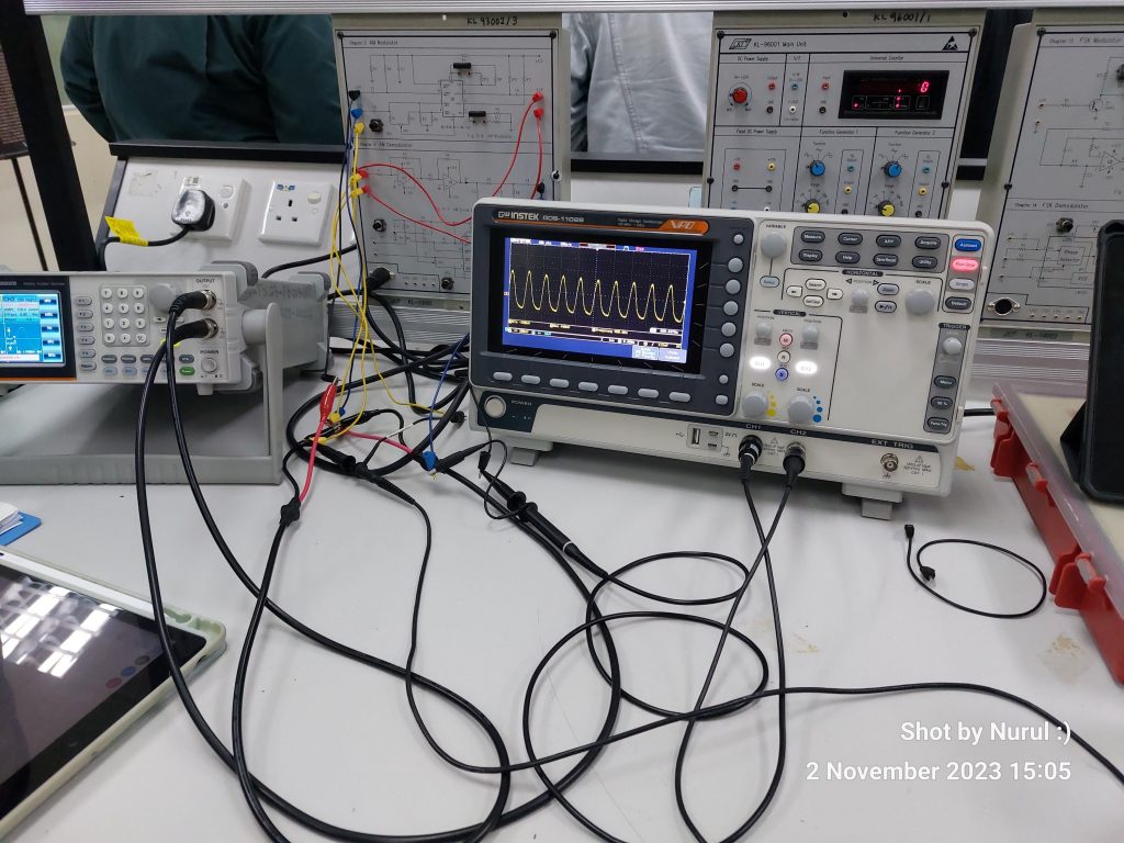
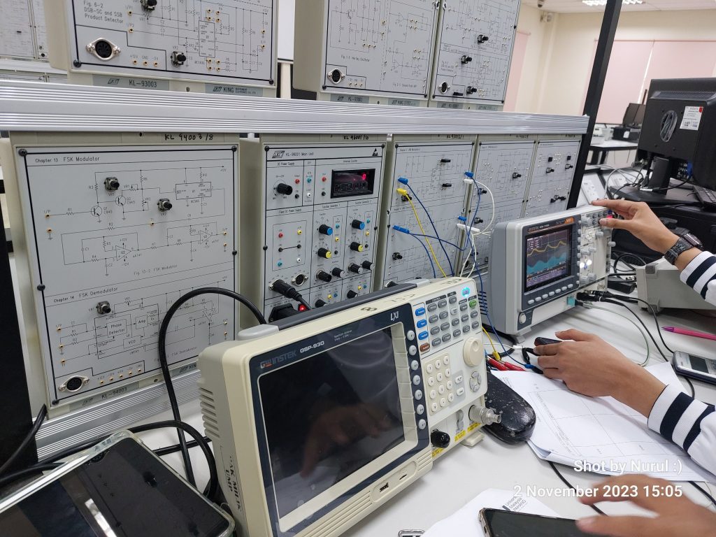
BTE 3233 Com System Design Laboratory – Amplitude Demodulation
1 – Understanding Amplitude Demodulation
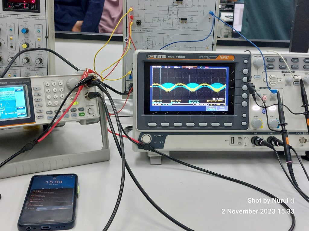
In signal processing, amplitude modulation (AM) is a fundamental technique that allows us to transmit information by varying the amplitude of a carrier signal. In ths lab session – dedicated to demodulation, understanding the process of amplitude demodulation is crucial. This process, often referred to as “demodulating” or “detecting,” involves the extraction of the original message signal from a modulated carrier signal. In this blog post, we will explore the concepts and methods behind amplitude demodulation, providing valuable insights for your lab session.
The Basics of Amplitude Modulation
Before delving into amplitude demodulation, let’s briefly revisit the concept of amplitude modulation. AM is a modulation technique that superimposes a message signal onto a carrier signal by varying the carrier’s amplitude in accordance with the message signal. This modulation process enables the transmission of analog information, such as audio signals, over radio waves.
2 – The Need for Demodulation
After transmission, the receiver needs to extract the original message signal, from the modulated carrier signal. This is where demodulation comes into play. The demodulation process is essential for various applications, including radio broadcasting, radar systems, and more.
3 – Amplitude Demodulation Techniques
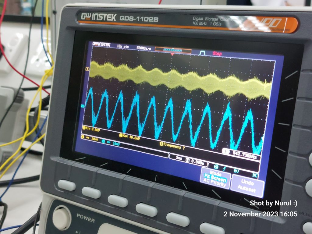
Amplitude demodulation is the process of retrieving the original message signal from an AM-modulated carrier signal. There are several methods to accomplish this task, and we’ll explore two common techniques:
4 – Envelope Detection
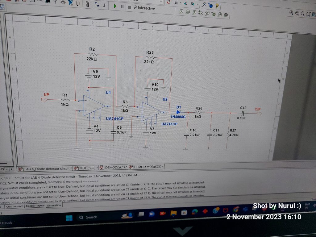
Envelope detection, also known as diode detection, is a straightforward method for demodulating AM signals. It relies on the fact that the envelope of an AM signal is proportional to the message signal.
The modulated signal is rectified using a diode, which essentially removes the negative component of the signal.
The resulting rectified signal is then low-pass filtered to smooth out the high-frequency components introduced during rectification.
The output of the low-pass filter represents the envelope of the original message signal.
Envelope detection is simple but effective and is commonly used in AM radio receivers.
5 – Synchronous Detection
Synchronous detection, also known as coherent detection, is a more sophisticated demodulation technique. It requires knowledge of the carrier signal’s frequency and phase.
The received modulated signal is mixed with a local oscillator signal at the carrier frequency. This mixing process shifts the carrier frequency down to baseband, resulting in a complex signal.
The complex signal is then low-pass filtered to obtain the real part, which represents the demodulated message signal. Synchronous detection is often used in high-performance AM demodulation and is more immune to noise and interference.
As you delve deeper into your lab session, remember that practical experience and experimentation play a significant role in mastering amplitude demodulation. By combining theoretical knowledge with hands-on practice, you’ll be well-equipped to tackle real-world challenges in signal processing and communication systems.
In the next session, we’ll look into Double SideBand Modulation.
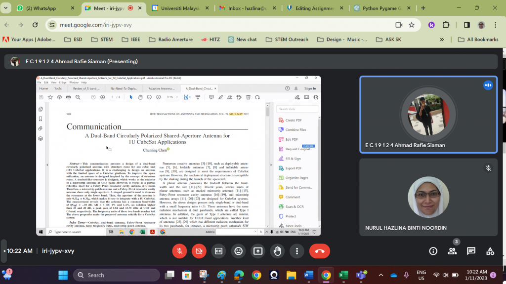
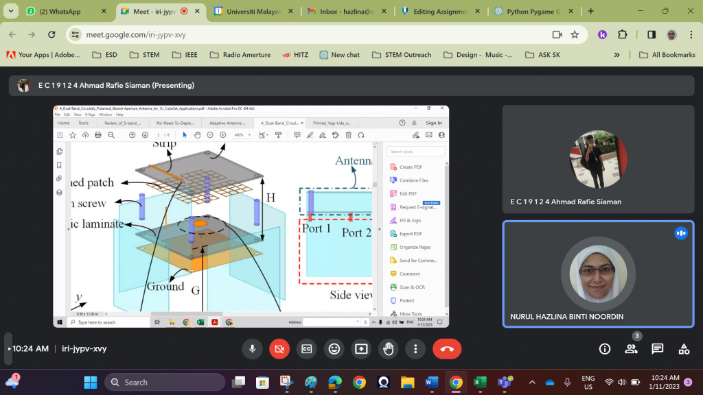
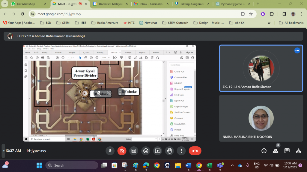
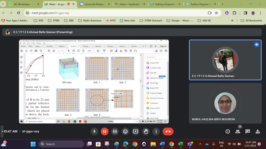
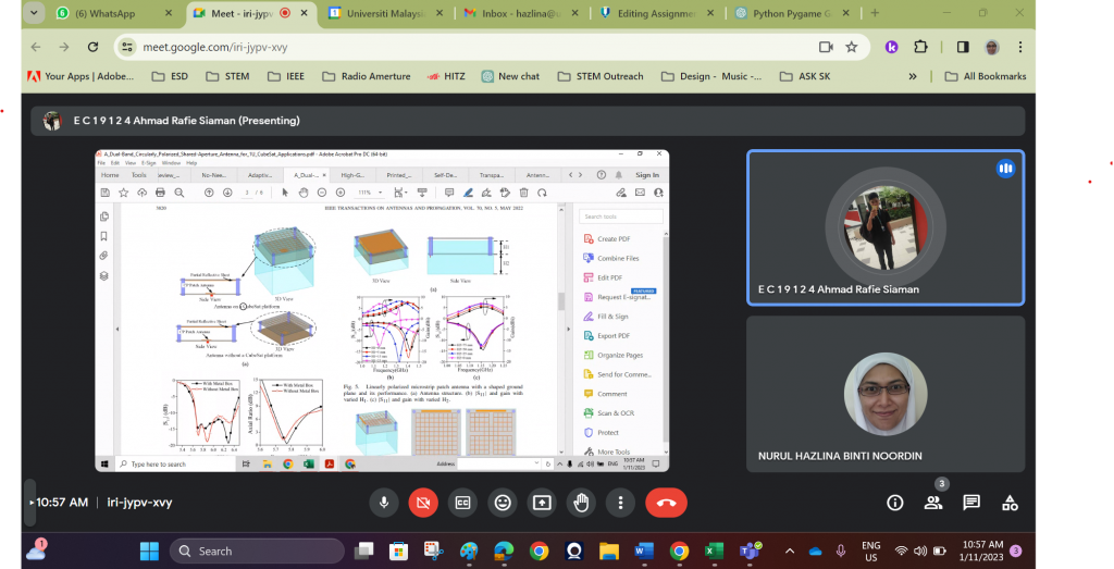
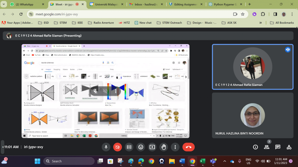
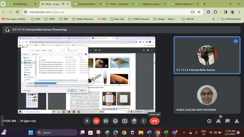
FYP Discussion Antenna Design for CubeSAT