The world is digital, but life is analog..


Well done =)


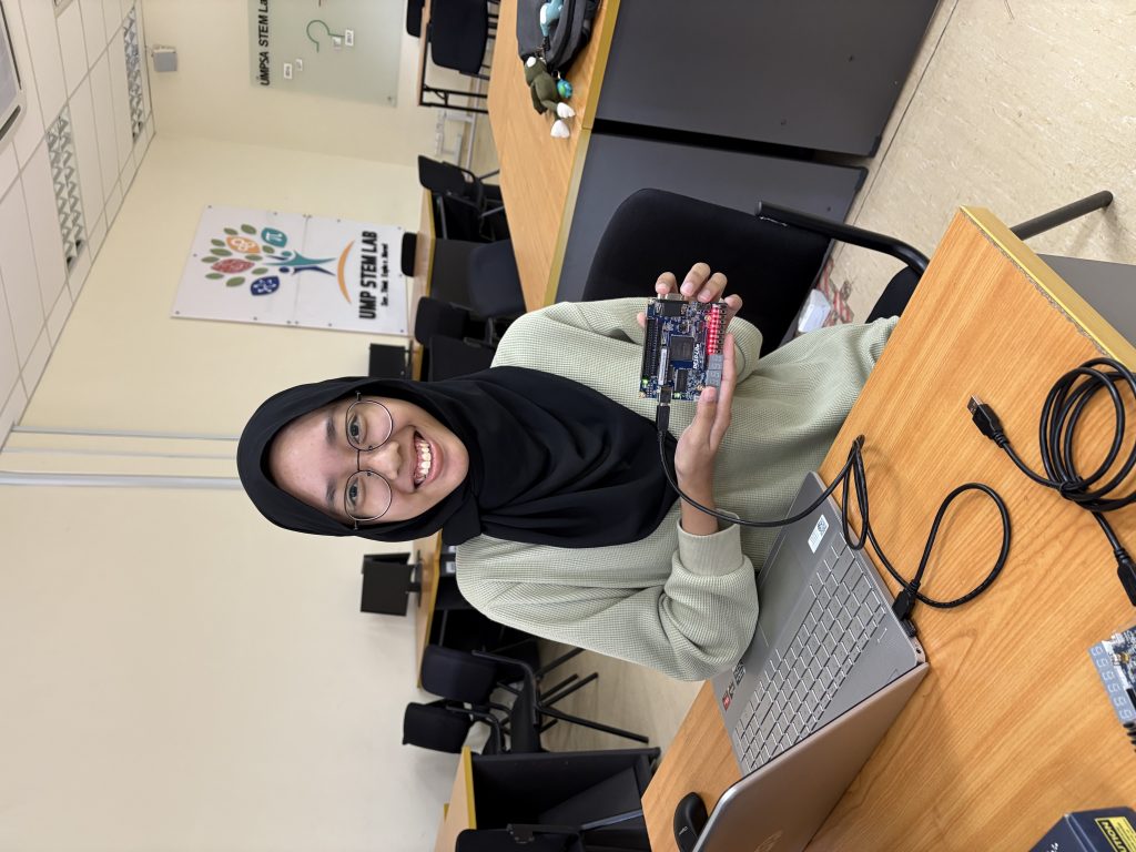
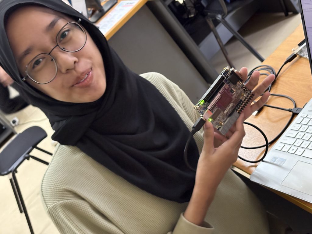
This week, students in the BHE3233: Hardware Description Language course took on three lab activities using the Altera DE10-Lite FPGA board. These labs were designed to deepen their understanding of digital logic design, from real hardware control to simulation-level debugging using testbenches.
Lab 1 Recap: LED Blinking with Verilog
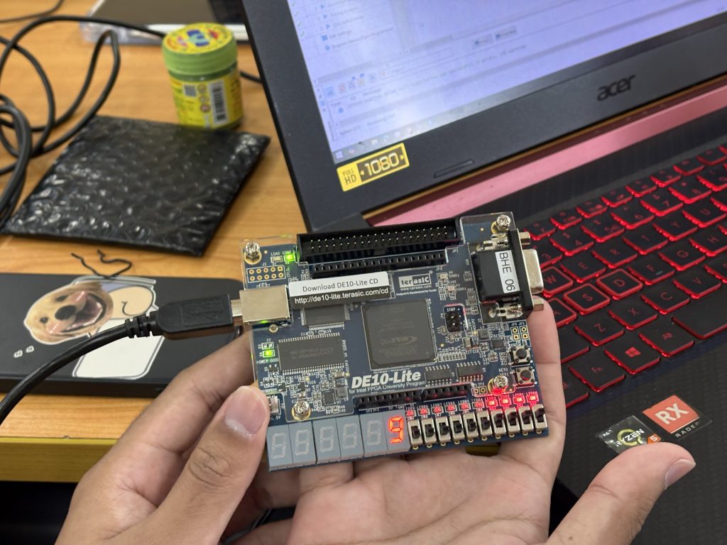
Students developed a Verilog module to blink the 10 onboard LEDs one at a time in sequence, based on a timing counter. The project introduced:
always @(posedge clk)
Counter logic for delay generation
reg and assign statements for driving output
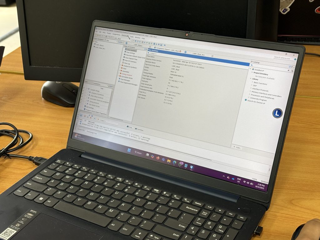
Pin assignment in Quartus
Lab 2 Recap: Real-Time LED Control Using Slider Switches
Students mapped the 10 slider switches directly to the 10 LEDs using basic combinational logic. This hands-on activity helped reinforce:
Use of continuous assignment (assign)
Bit-wise mapping between inputs and outputs
How to apply pin mapping in Quartus for SW[9:0] and LED[9:0]
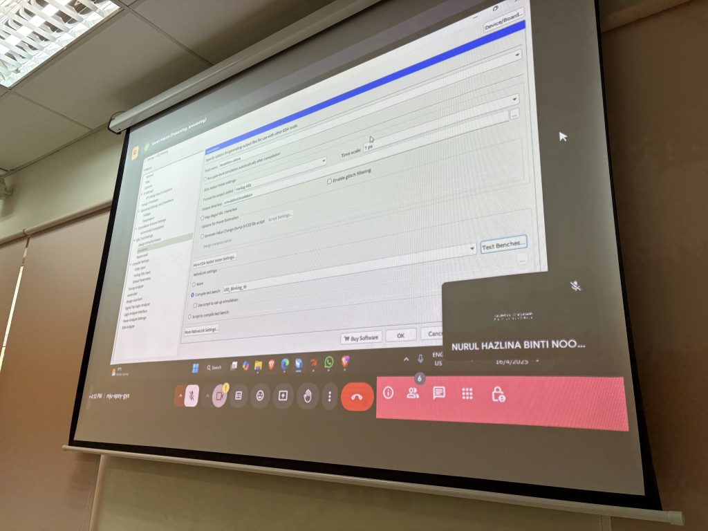
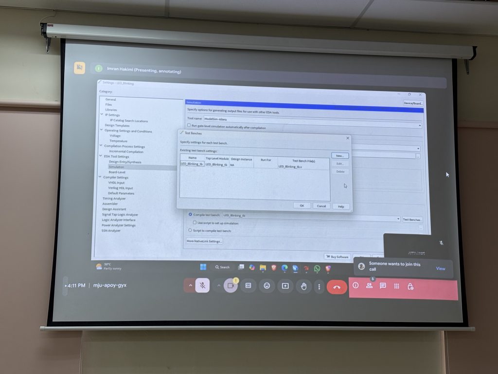
Lab 3 Preview: Writing a Testbench & Understanding Timing Diagrams
To develop a testbench for both Lab 1 (LED Blinking) and Lab 2 (Switch to LED) designs, simulate the behavior using ModelSim, and interpret the timing diagram (waveform) to verify correct functionality.
ModelSim (Intel FPGA Edition) for running simulations
Waveform viewer for analyzing signal transitions over time
To Do
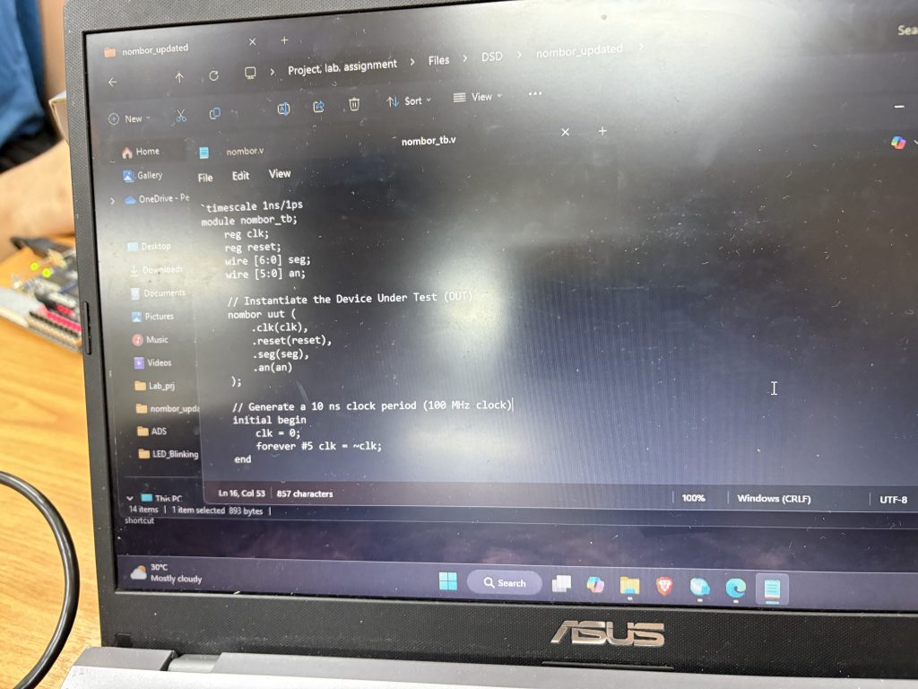
Create a Testbench File for Each Design
Instantiate the DUT (Design Under Test)
Simulate clk signal (for Lab 1)
Apply appropriate test vectors (SW[9:0]) for Lab 2
Run Simulation
Launch ModelSim from Quartus
Compile and simulate the testbench
Observe and save waveform output
Analyze the Timing Diagram
For Lab 1: Check the blinking behavior of LED[current_led]
For Lab 2: Confirm that LED outputs match the SW inputs at each simulation step
Learning Outcome:
Students will visually interpret digital signal transitions through the waveform viewer in ModelSim, reinforcing:
Propagation delay
Clock edge behavior
Signal assertion and response timing
Apply Hardware Description Languages (HDL) to design, simulate, and verify digital circuits at the Register Transfer Level (RTL).
Lab 3 bridges the gap between coding and functional verification. Students now understand how simulation helps confirm logic correctness before moving to hardware.
What’s Next?
Next week, you will begin working on combinational building blocks like adders and multipliers, then explore state machines and RTL synthesis in depth.
and Midterm Test 🙂
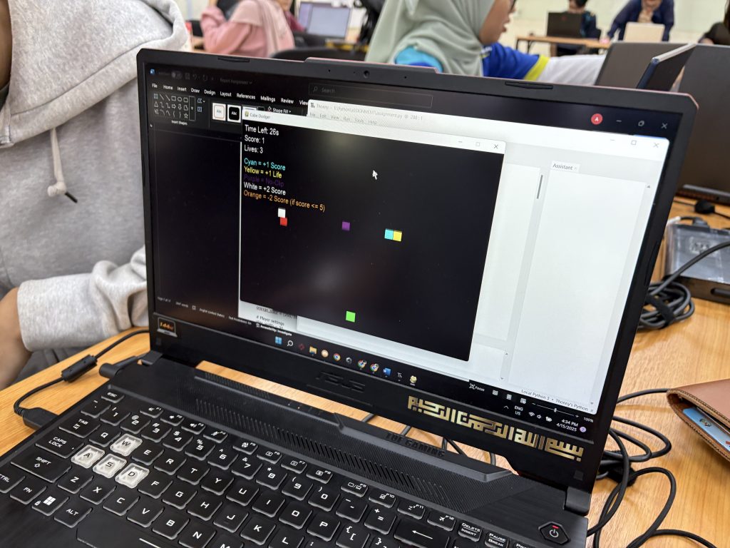
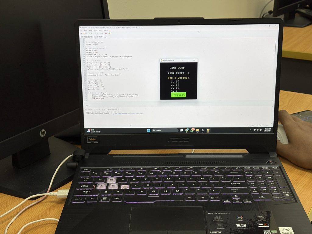
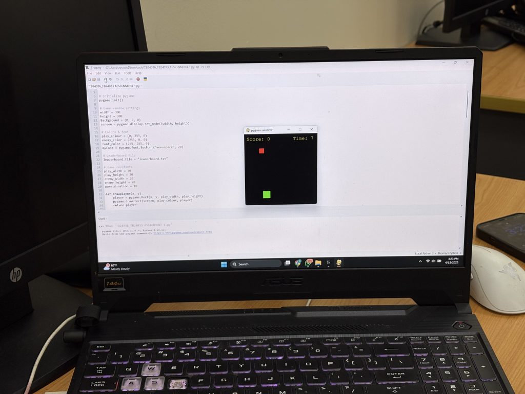
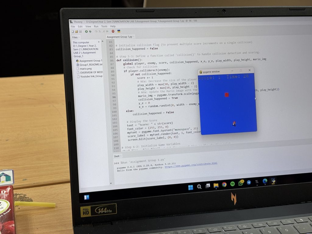
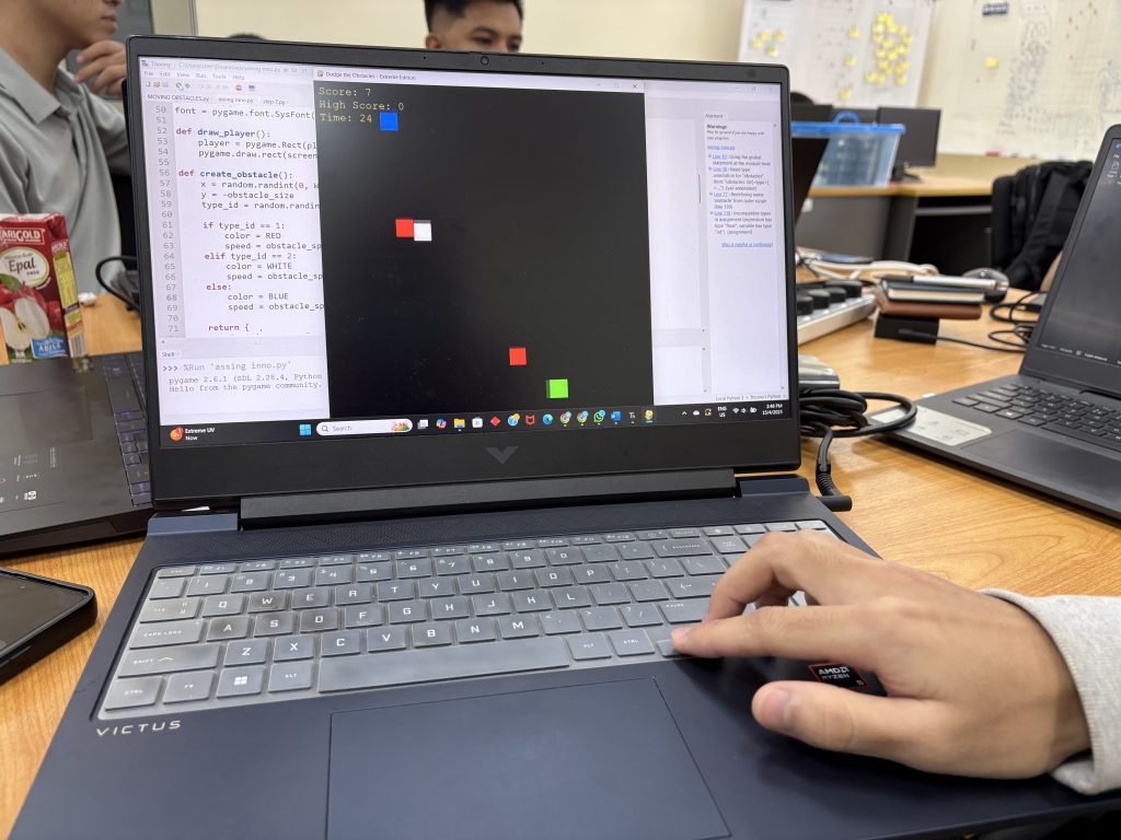
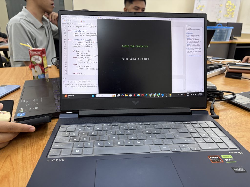
Today’s BTE1522 session was all about taking the class assignment slider game project to the next level—through code modification and applied programming. With their foundational game now complete (step 7), students were given a list of features to implement, each requiring a combination of Python programming concepts, critical thinking, and a bit of creativity!
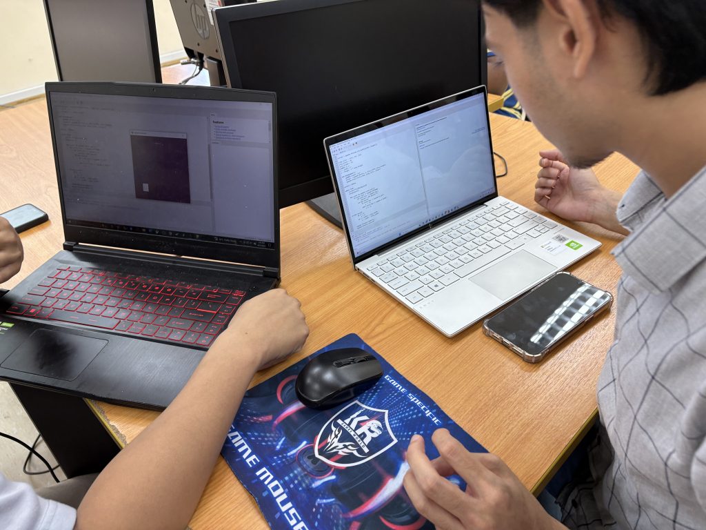
In groups, students worked on implementing new functionalities into their existing slider game projects. Each modification involved one or more Python concepts and gave students the opportunity to explore real problem solving through game design.
| No. | Feature | Programming Concepts Explored |
|---|---|---|
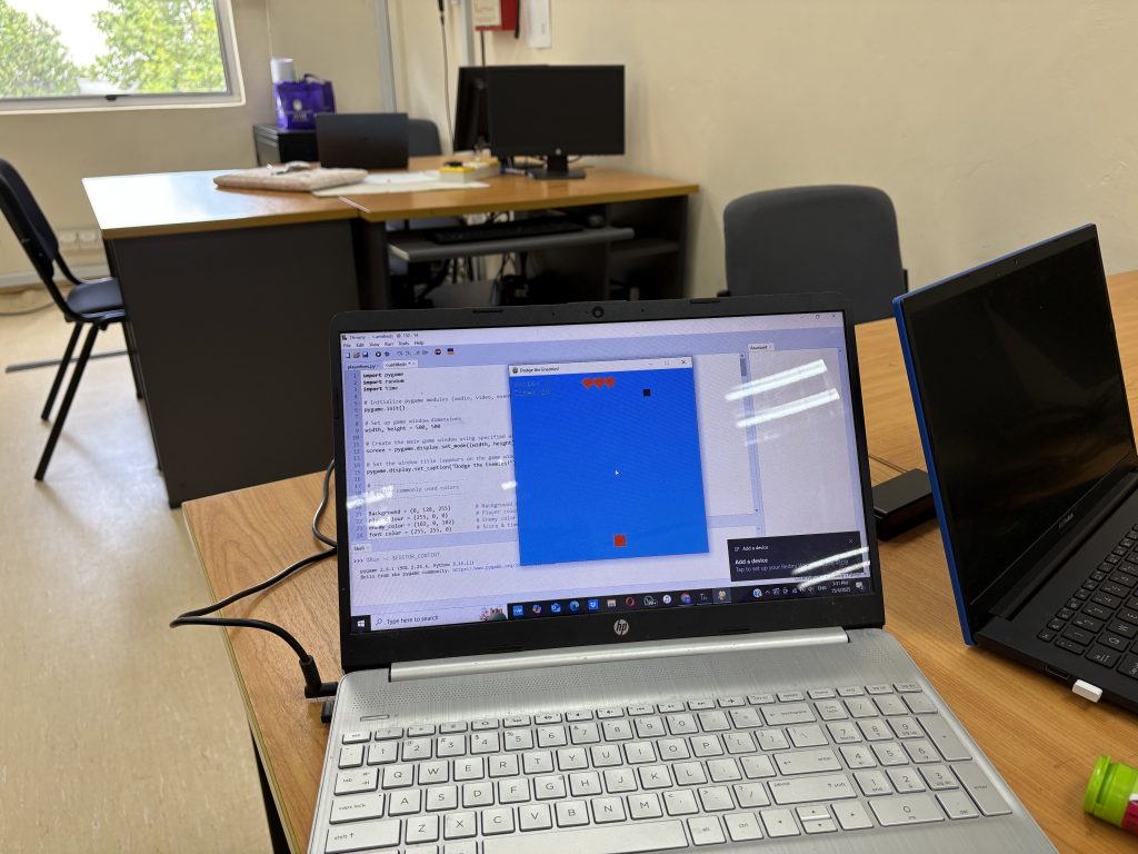
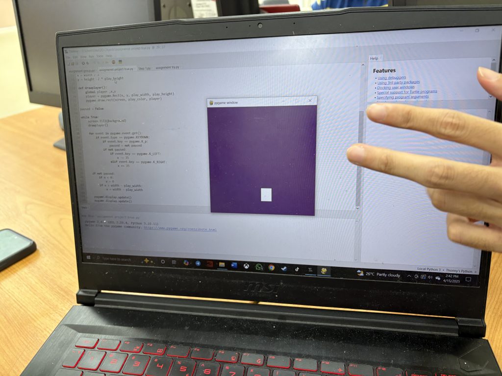
| 1 | Customizable Player Appearance | User input, rendering, player attributes |
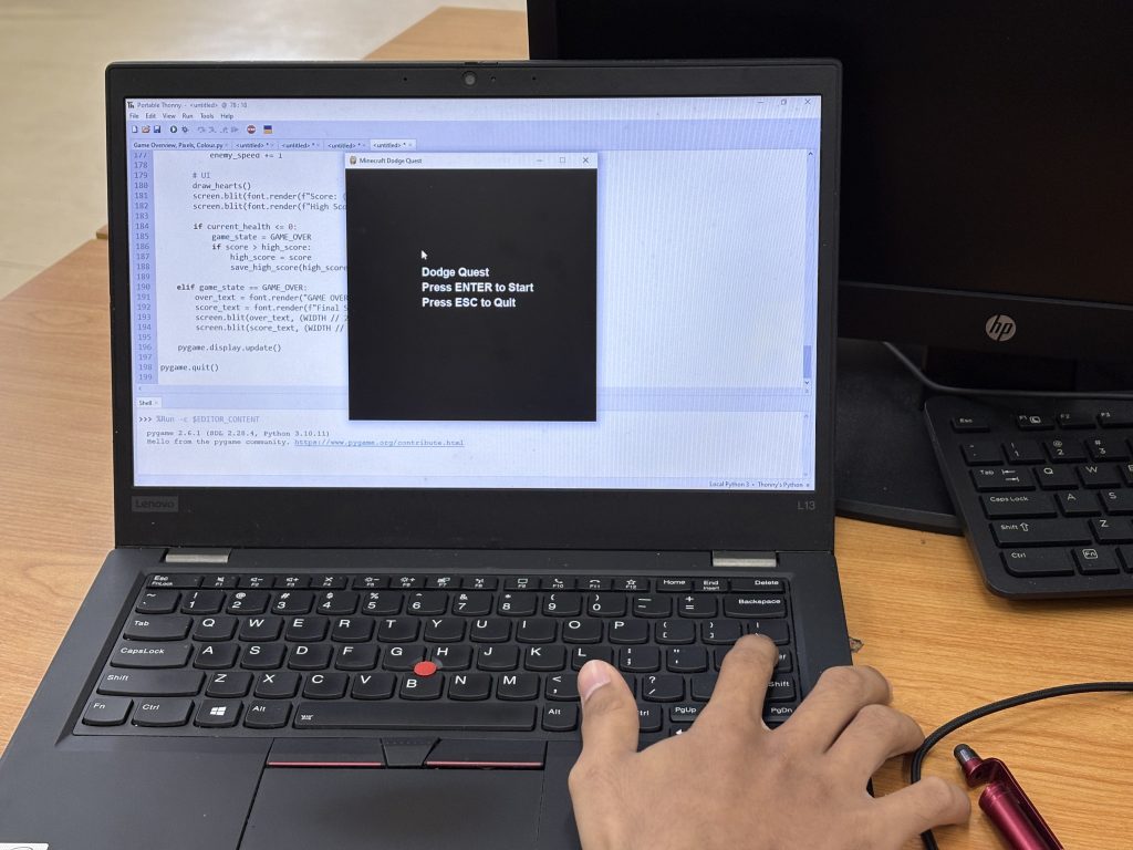
| 2 | Game Pause and Resume | Event handling, game states, timers |
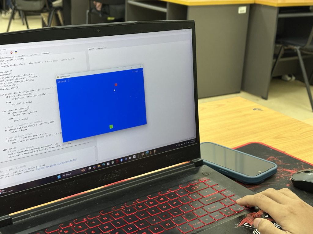
| 4 | Moving Obstacles | Movement logic, collision detection, timers |
| 5 | Enemy Movement Patterns | Custom functions, coordinate systems |
| 9 | Special Attacks for Player | Event handling, rendering, custom functions |
| 10 | Multiplayer Mode | Input handling, game states |
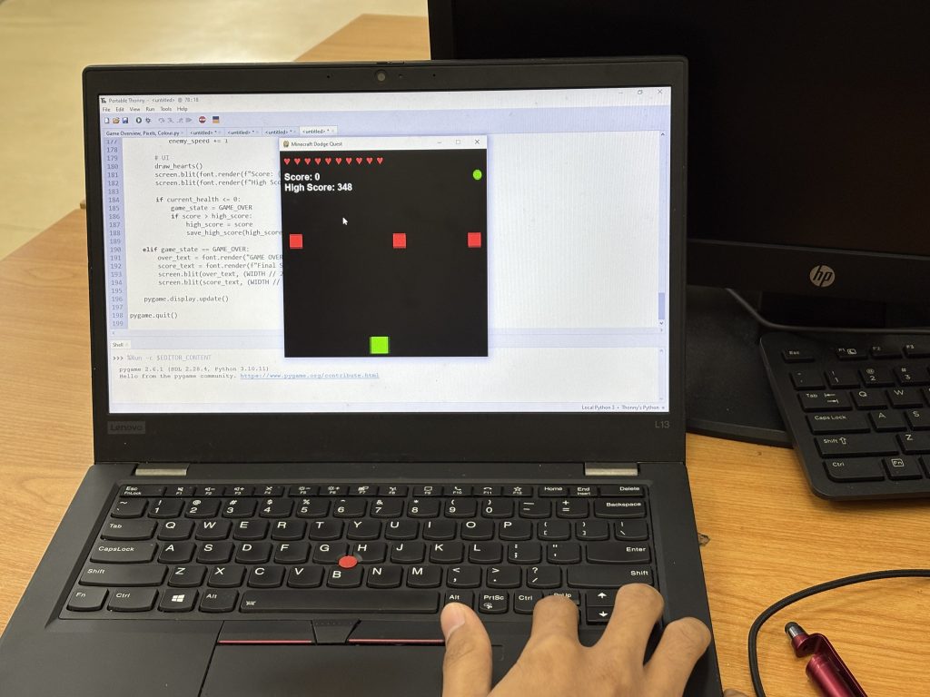
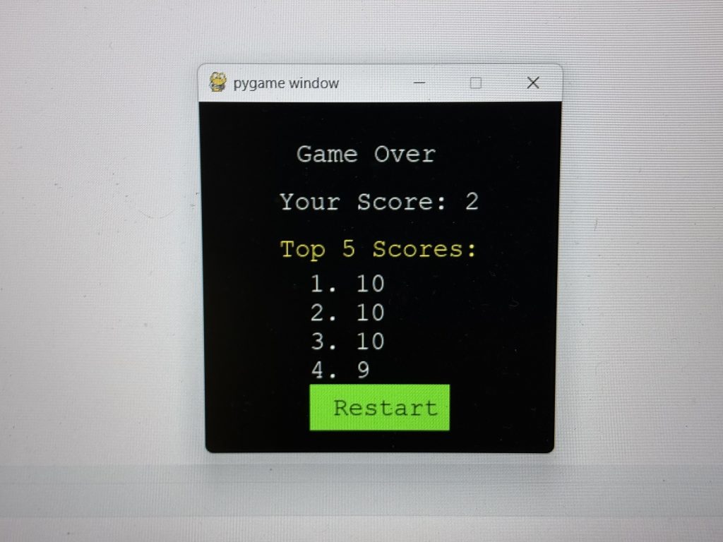
| 14 | Leaderboard Display | File handling, string formatting, data persistence |
| 17 | Player Lives System | Conditionals, variables, state management |
| 18 | Health Bar Display | Rendering, variables, collision |
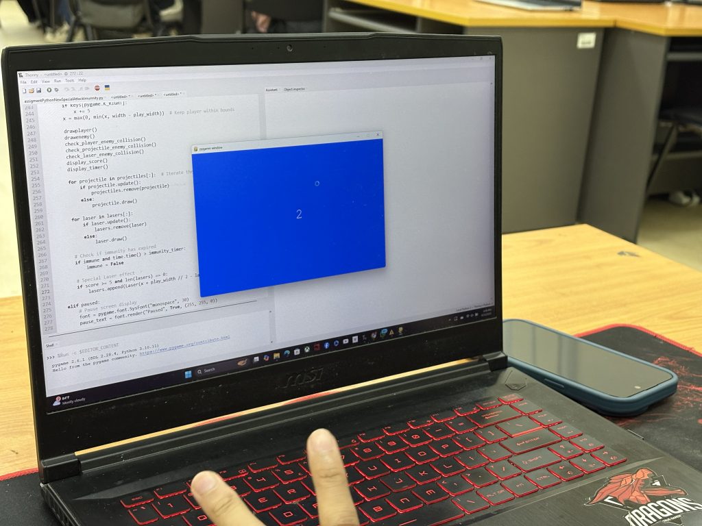
| 20 | Level System | Level management, difficulty scaling |
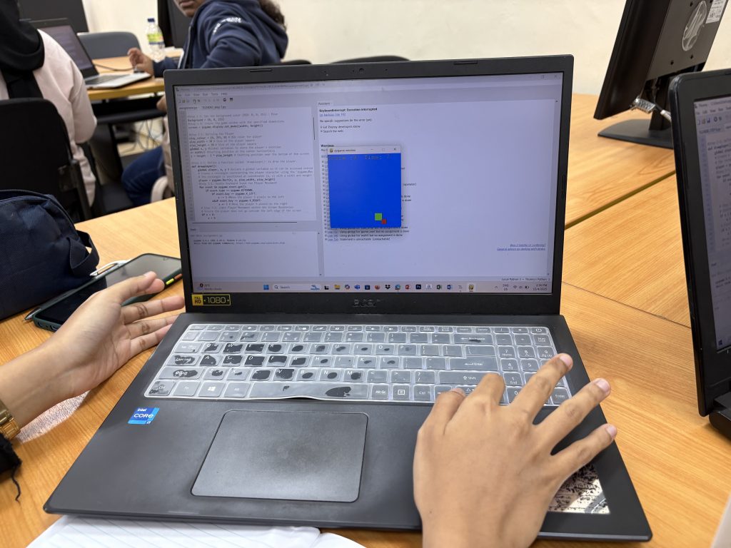
Each team selected a feature, explored the Python logic behind it, and began integrating it into their existing codebase. It was rewarding to see teams applying what they’ve learned about loops, conditionals, functions, and event handling in a hands-on way.
To push their understanding further, every group was given a “Level-Up” challenge—a task that required enhancing or optimizing their chosen modification. These challenges were designed to:
Encourage deeper reflection on Python logic
Promote code efficiency and modular design
Help students explain the relationship between what their game does and the Python concept it’s based on
For example:
Teams working on player lives were challenged to add a visual life tracker (hearts or icons).
Those creating a multiplayer mode were asked to explore keyboard conflict resolution and responsive game states.
The group managing the leaderboard was tasked to sort and persist scores across sessions.
Throughout the activity, students were encouraged to ask themselves:
“What Python concept is being used here?”
“How can I break down this functionality into smaller functions?”
“How can I make this scalable if I wanted to add more features?”
This reflection not only reinforces their coding skills but also helps students become intentional learners, capable of connecting code to concept.
To all the students, please submit your work via Tinta. make sure to include:-