Today’s class focused on one of the core topics in digital system design—Finite State Machines (FSM)—through an engaging and practical activity: building a 101 sequence detector using a Moore machine.
We began with a recap of FSM fundamentals—specifically the Moore machine, where outputs are solely determined by the current state. This conceptual understanding paved the way for the day’s main activity: designing and testing a sequence detector that identifies the binary pattern 101.
Key areas explored:
-
State transition diagrams and state encoding
-
Implementation using case statements
-
Exploring both dataflow-style FSM and conditional (if-else) statement-based FSMs
-
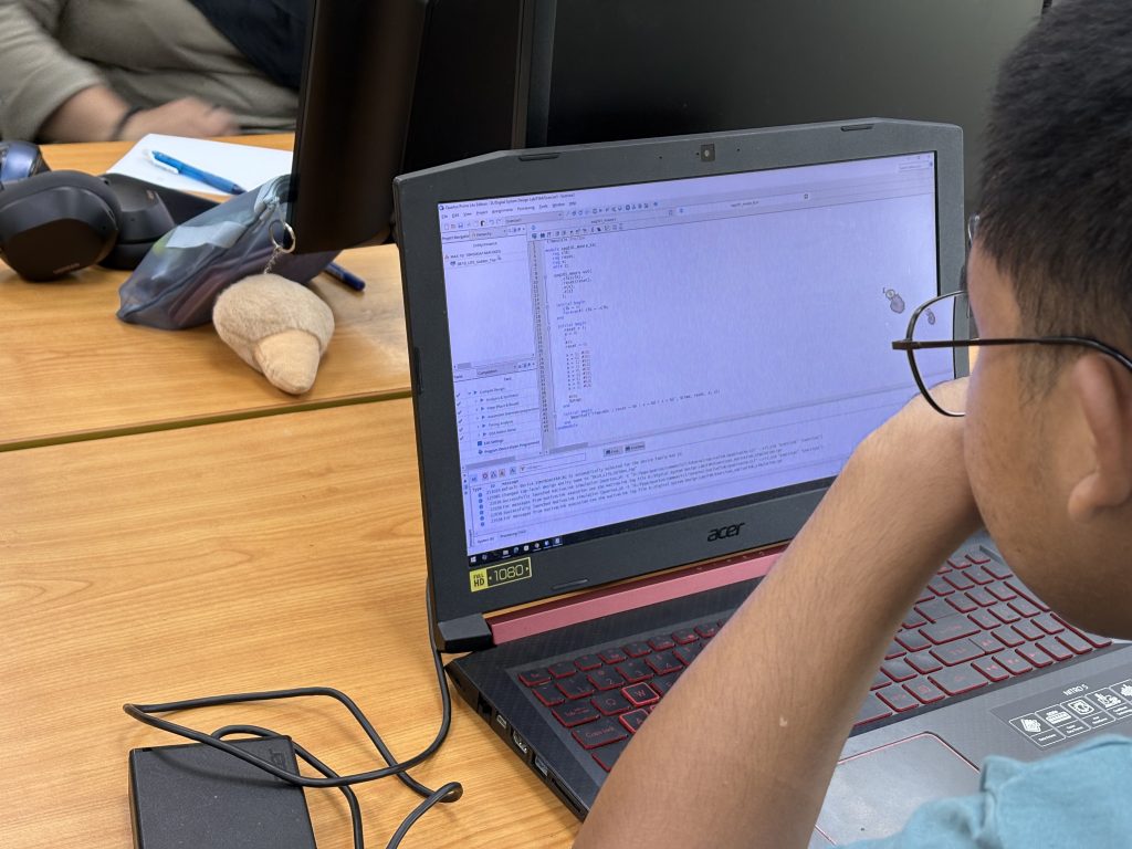
Synthesizing and testing using Quartus Prime
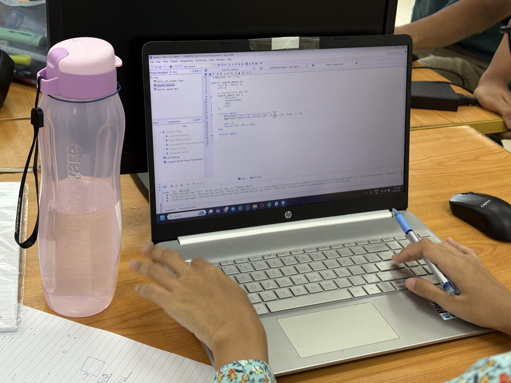
Students designed the FSM in Verilog using Quartus. The Moore machine was structured with three states to detect the pattern:
-
S0 – Initial state
-
S1 – Received ‘1’
-
S2 – Received ‘10’
When the full sequence 101 was detected, the FSM output went high.
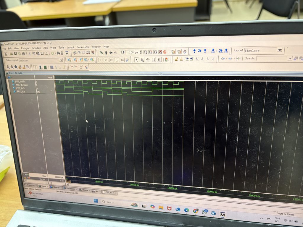
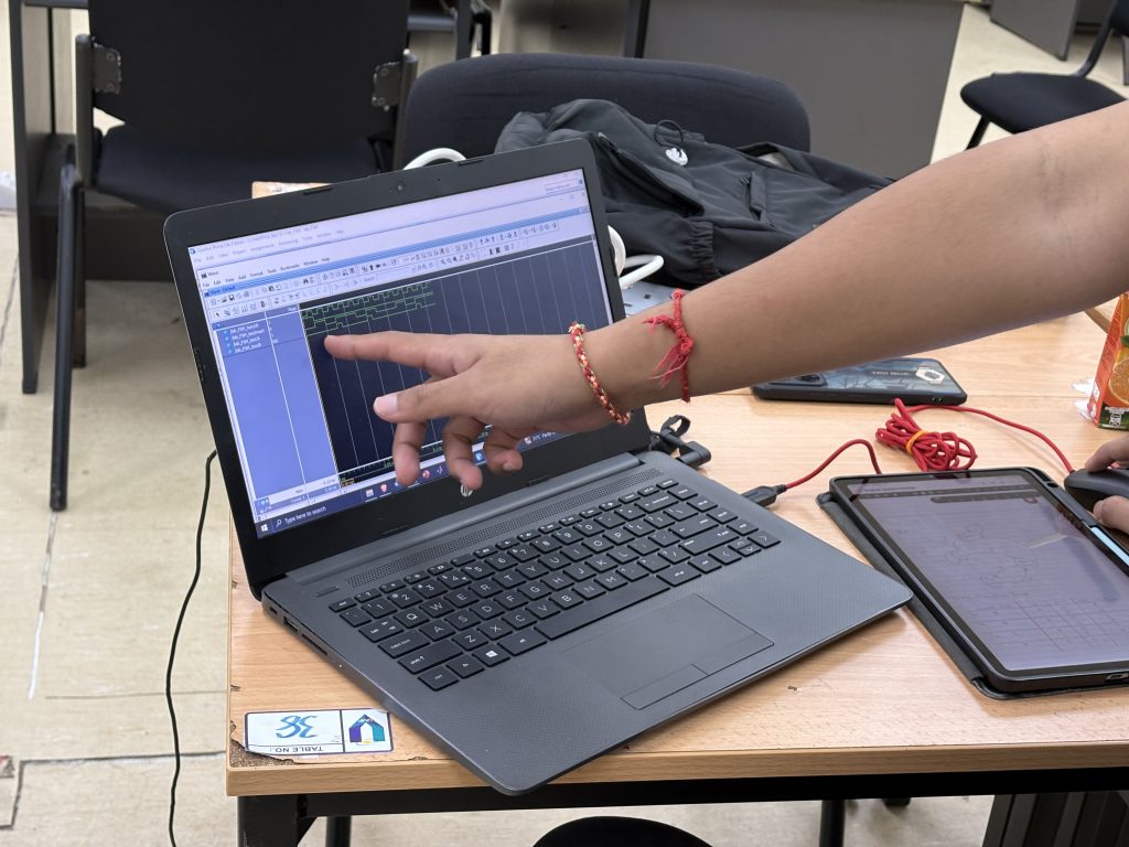
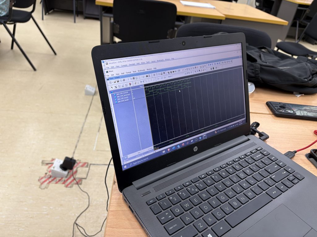
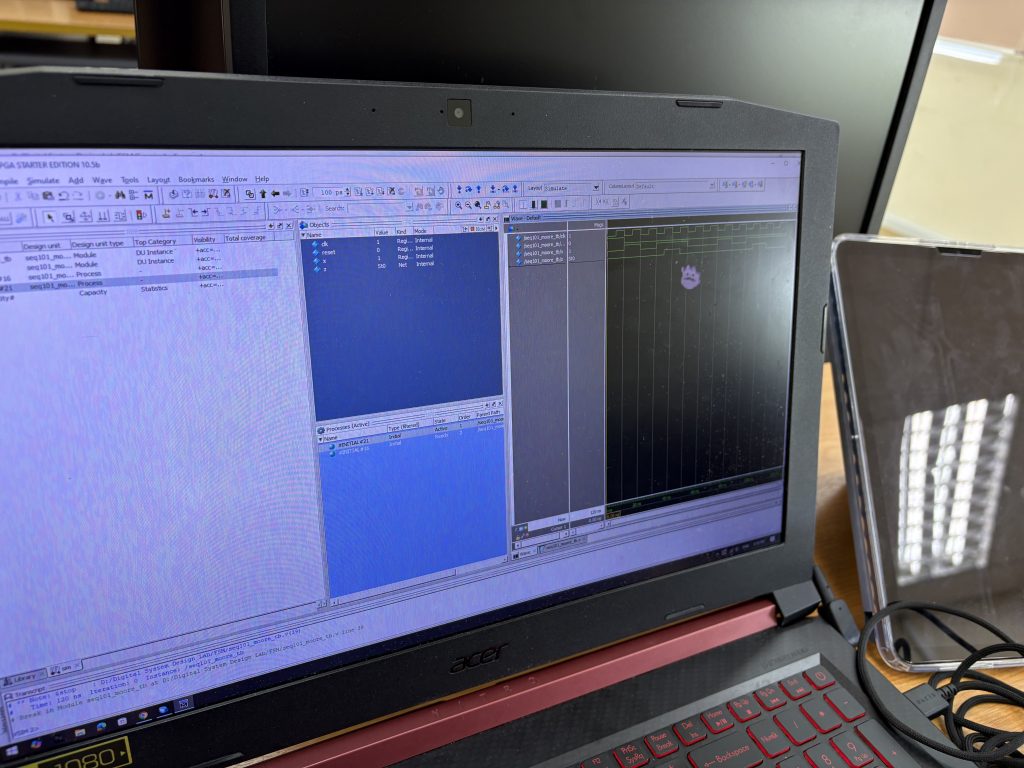
Simulation and Testbench Creation
To validate the design, students created testbenches that simulated input sequences. Using ModelSim, they:
-
Applied a sequence of 0s and 1s to the
ininput -
Monitored state transitions
-
Verified output pulses when
101was detected
This phase helped students understand the role of simulation in design verification and how FSMs react to clocked inputs in real time.
The case statement simplified FSM implementation, especially when compared to nested conditional (if-else) logic. They also discussed how a well-structured FSM can lead to clean, readable, and maintainable RTL code—an essential practice in real-world design.
Learning Outcomes
By the end of the session, students were able to:
-
Describe and implement Moore FSMs in Verilog
-
Translate a sequence detection problem into state transitions
-
Use Quartus for synthesis and ModelSim for simulation
-
Compare dataflow FSM vs. conditional FSM modeling